How to Use Adafruit Mini 8x8 LED Matrix Backpack Yellow: Examples, Pinouts, and Specs
Introduction
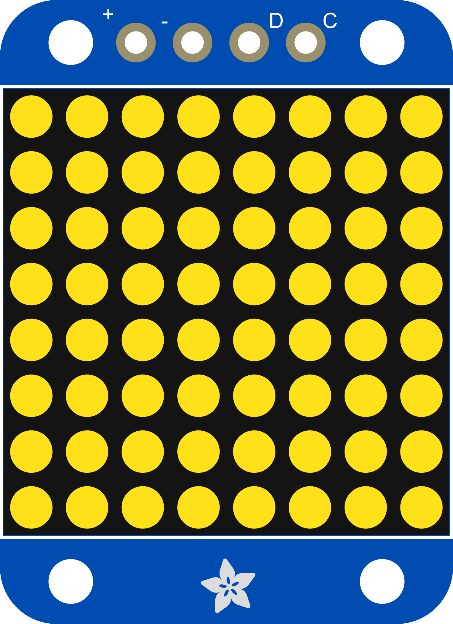
The Adafruit Mini 8x8 LED Matrix Backpack Yellow is a versatile and compact electronic component designed for displaying graphical information in a simple and effective way. This module is equipped with a matrix of 8x8 yellow LEDs, controlled by an integrated driver chip that simplifies the process of interfacing with microcontrollers, such as the Arduino UNO. Common applications include creating small displays for clocks, counters, and games, or as a visual output for sensors and other electronic devices.
Explore Projects Built with Adafruit Mini 8x8 LED Matrix Backpack Yellow

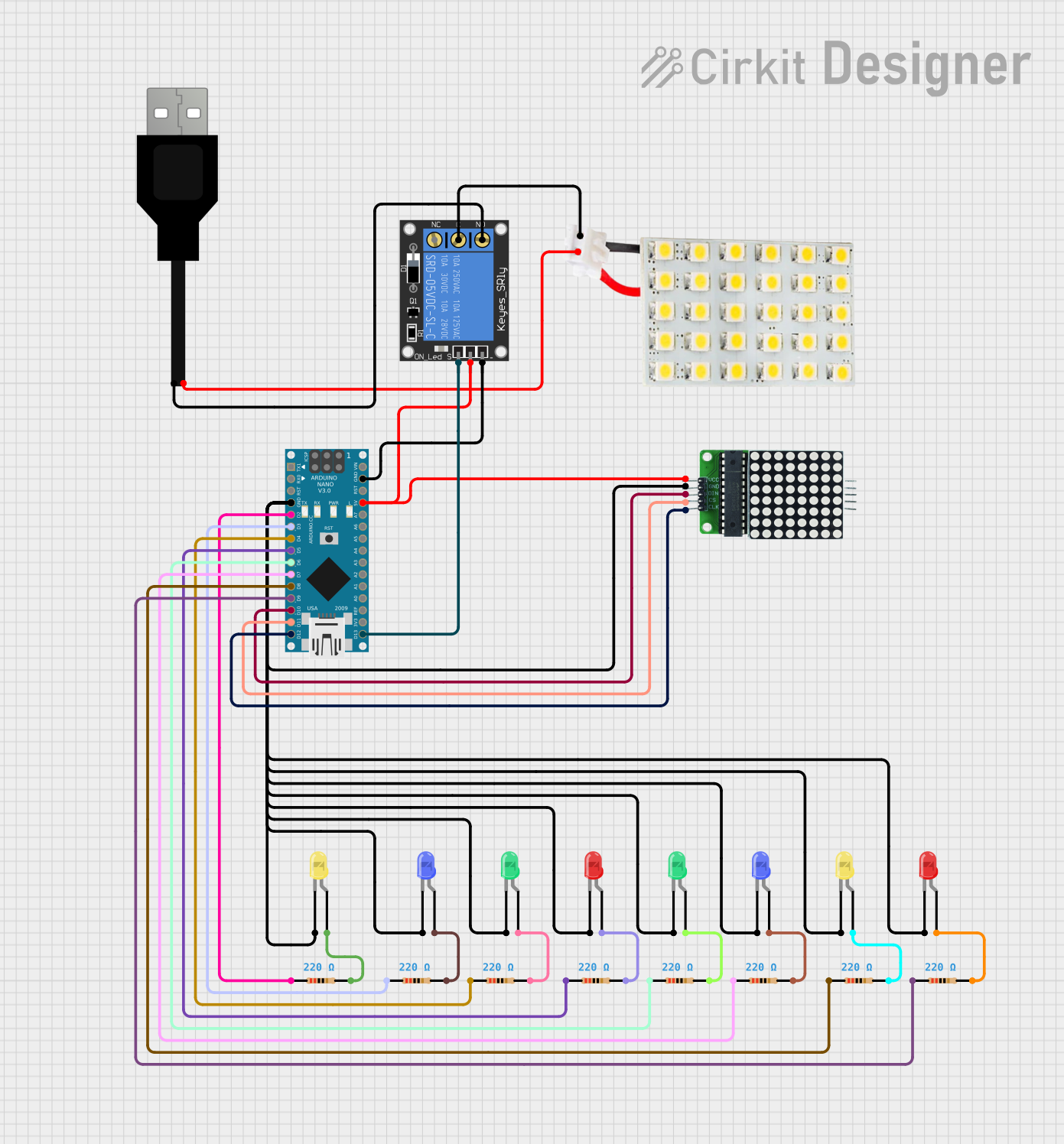
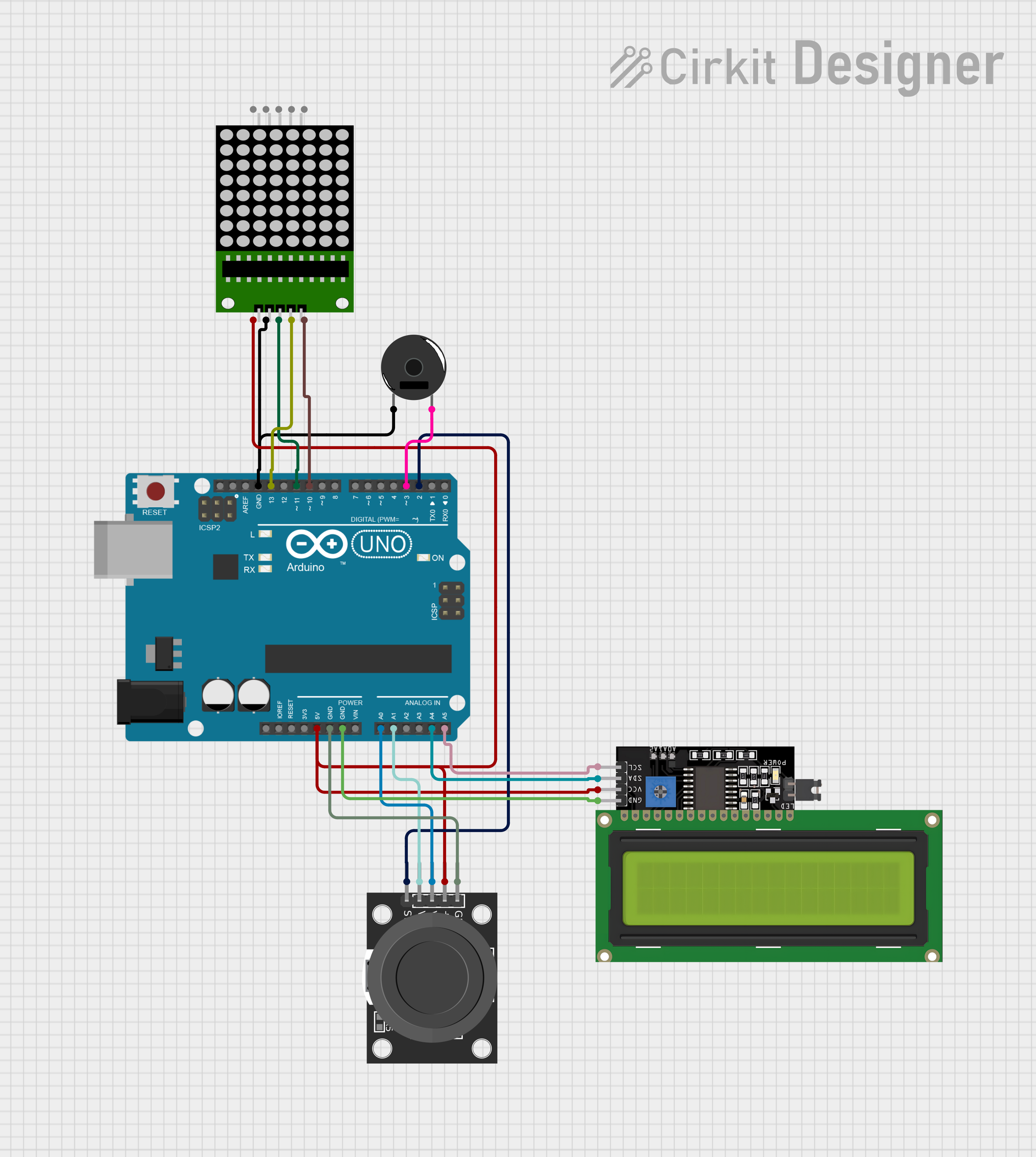

Explore Projects Built with Adafruit Mini 8x8 LED Matrix Backpack Yellow
Technical Specifications
Key Technical Details
- LED Color: Yellow
- Matrix Size: 8x8 LEDs
- Operating Voltage: 4.5V - 5.5V
- Max Current (per LED): 30mA
- Communication: I2C interface
- Driver Chip: HT16K33
Pin Configuration and Descriptions
| Pin Number | Name | Description |
|---|---|---|
| 1 | GND | Ground connection |
| 2 | VCC | Power supply (4.5V - 5.5V) |
| 3 | SDA | I2C data line |
| 4 | SCL | I2C clock line |
Usage Instructions
Interfacing with Arduino
To use the Adafruit Mini 8x8 LED Matrix Backpack with an Arduino UNO, follow these steps:
Connect the Module:
- Connect VCC to 5V on the Arduino.
- Connect GND to one of the GND pins on the Arduino.
- Connect SDA to A4 (SDA) on the Arduino.
- Connect SCL to A5 (SCL) on the Arduino.
Install the Adafruit LED Backpack Library:
- Open the Arduino IDE.
- Go to
Sketch>Include Library>Manage Libraries... - Search for "Adafruit LED Backpack" and install the library.
Programming the Arduino:
- Include the Adafruit LED Backpack and GFX libraries in your sketch.
- Initialize the display object and begin communication.
- Use the library functions to control the LEDs.
Example Code
#include <Wire.h>
#include <Adafruit_GFX.h>
#include <Adafruit_LEDBackpack.h>

Adafruit_8x8matrix matrix = Adafruit_8x8matrix();

void setup() {
  matrix.begin(0x70); // Initialize the display with the I2C address (default)
}

void loop() {
  matrix.clear(); // Clear the buffer
  matrix.drawPixel(0, 0, LED_ON); // Turn on a single LED at (0,0)
  matrix.writeDisplay(); // Write the buffer to the display
  delay(500);
  matrix.clear(); // Clear the buffer
  matrix.writeDisplay(); // Write the buffer to the display
  delay(500);
}
Important Considerations and Best Practices
- Ensure that the power supply voltage does not exceed the recommended range to prevent damage to the LEDs.
- When connecting multiple LED matrices, make sure to set unique I2C addresses for each one.
- Avoid drawing too much current from the Arduino by lighting up too many LEDs at maximum brightness simultaneously.
Troubleshooting and FAQs
Common Issues
LEDs Not Lighting Up:
- Check the wiring and ensure proper connections to the Arduino.
- Verify that the correct I2C address is used in the code.
- Ensure the power supply is within the specified voltage range.
Dim or Flickering LEDs:
- Check for a stable power supply.
- Adjust the brightness in the code if necessary.
Solutions and Tips for Troubleshooting
- Use the
Seriallibrary to output debug information to the Arduino IDE Serial Monitor. - If using multiple devices on the I2C bus, ensure there are no address conflicts.
- Check for soldering issues on the matrix pins if it was self-assembled.
FAQs
Q: Can I change the brightness of the LEDs?
- A: Yes, the Adafruit LED Backpack library provides functions to adjust the brightness.
Q: How many of these matrices can I chain together?
- A: You can chain up to 8 matrices on the same I2C bus by assigning unique addresses to each.
Q: Can this matrix display colors other than yellow?
- A: No, this specific model only contains yellow LEDs. However, other models with different colored LEDs are available.
For further assistance, consult the Adafruit support forums or the detailed guides available on the Adafruit website.