
How to Use IR GP2Y0A21YK0F : Examples, Pinouts, and Specs
 Design with IR GP2Y0A21YK0F in Cirkit Designer
Introduction
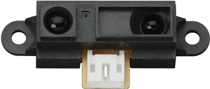
The GP2Y0A21YK0F is an infrared distance sensor capable of measuring distances between 10 cm and 80 cm. It operates by emitting infrared light through an LED and detecting the reflected light using a phototransistor. The sensor outputs an analog voltage that corresponds to the distance of the detected object, making it ideal for applications requiring non-contact distance measurement.
Explore Projects Built with IR GP2Y0A21YK0F
 Open Project in Cirkit Designer
 Open Project in Cirkit Designer
 Open Project in Cirkit Designer
 Open Project in Cirkit Designer
Explore Projects Built with IR GP2Y0A21YK0F
Open Project in Cirkit DesignerOpen Project in Cirkit DesignerOpen Project in Cirkit DesignerOpen Project in Cirkit DesignerCommon Applications
- Obstacle detection in robotics
- Proximity sensing in automation systems
- Object detection in consumer electronics
- Distance measurement in industrial equipment
Technical Specifications
Below are the key technical details of the GP2Y0A21YK0F sensor:
| Parameter | Value |
|---|---|
| Operating Voltage | 4.5 V to 5.5 V |
| Average Current Consumption | 30 mA (typical) |
| Output Voltage Range | 0.4 V to 2.8 V (analog) |
| Measuring Range | 10 cm to 80 cm |
| Response Time | 38 ms |
| Operating Temperature Range | -10°C to +60°C |
| Dimensions | 29.5 mm × 13 mm × 21.6 mm |
Pin Configuration and Descriptions
The GP2Y0A21YK0F has a 3-pin JST connector. The pinout is as follows:
| Pin | Name | Description |
|---|---|---|
| 1 | VCC | Power supply input (4.5 V to 5.5 V) |
| 2 | GND | Ground connection |
| 3 | VOUT | Analog voltage output proportional to distance |
Usage Instructions
How to Use the Component in a Circuit
- Power Supply: Connect the VCC pin to a 5 V power source and the GND pin to ground.
- Output Signal: Connect the VOUT pin to an analog input pin of a microcontroller (e.g., Arduino) to read the distance as an analog voltage.
- Distance Calculation: Use the sensor's output voltage to calculate the distance. The relationship between voltage and distance is non-linear and can be approximated using a lookup table or a mathematical formula.
Important Considerations and Best Practices
- Avoid Ambient Light Interference: The sensor's performance may degrade in environments with strong ambient light. Use it in controlled lighting conditions for best results.
- Mounting: Ensure the sensor is mounted securely and aligned properly to avoid inaccurate readings.
- Voltage Regulation: Use a stable 5 V power supply to prevent fluctuations in the output signal.
- Distance Range: Do not use the sensor for distances below 10 cm or above 80 cm, as the output may become unreliable.
Example Code for Arduino UNO
Below is an example of how to use the GP2Y0A21YK0F with an Arduino UNO to measure distance:
// Define the analog pin connected to the sensor's VOUT pin
const int sensorPin = A0;

void setup() {
  Serial.begin(9600); // Initialize serial communication at 9600 baud
}

void loop() {
  int sensorValue = analogRead(sensorPin); // Read the analog value from the sensor
  float voltage = sensorValue * (5.0 / 1023.0); // Convert the analog value to voltage

  // Approximate distance calculation based on sensor's characteristics
  float distance = 27.86 / (voltage - 0.42); // Example formula for distance in cm

  // Print the distance to the Serial Monitor
  Serial.print("Distance: ");
  Serial.print(distance);
  Serial.println(" cm");

  delay(100); // Wait for 100 ms before the next reading
}
Note: The formula used in the code is an approximation. For more accurate results, refer to the sensor's datasheet and use a calibration curve.
Troubleshooting and FAQs
Common Issues
No Output or Incorrect Readings
- Cause: Incorrect wiring or loose connections.
- Solution: Double-check the wiring and ensure all connections are secure.
Fluctuating Output
- Cause: Unstable power supply or electrical noise.
- Solution: Use a decoupling capacitor (e.g., 10 µF) across the power supply pins.
Inaccurate Distance Measurements
- Cause: Object is outside the sensor's range (10 cm to 80 cm).
- Solution: Ensure the object is within the specified range.
Interference from Ambient Light
- Cause: Strong ambient light affecting the sensor's performance.
- Solution: Shield the sensor from direct sunlight or bright light sources.
FAQs
Q1: Can the GP2Y0A21YK0F detect transparent objects?
A1: No, the sensor may not reliably detect transparent or highly reflective objects due to insufficient reflected infrared light.
Q2: How do I improve the accuracy of distance measurements?
A2: Use a calibration curve specific to your application and environment. Avoid using the sensor in extreme lighting conditions.
Q3: Can I use this sensor with a 3.3 V microcontroller?
A3: The sensor requires a 5 V power supply, but the output voltage can be read by a 3.3 V microcontroller if the analog input pin supports it. Use a level shifter if necessary.
Q4: What is the response time of the sensor?
A4: The sensor has a response time of approximately 38 ms, making it suitable for real-time applications.