Cirkit Designer Logo
Cirkit Designer
Your all-in-one circuit design IDE
Home / 
Component Documentation

How to Use Stepdown 18v to 5V: Examples, Pinouts, and Specs

Image of Stepdown 18v to 5V
Cirkit Designer LogoDesign with Stepdown 18v to 5V in Cirkit Designer

Introduction

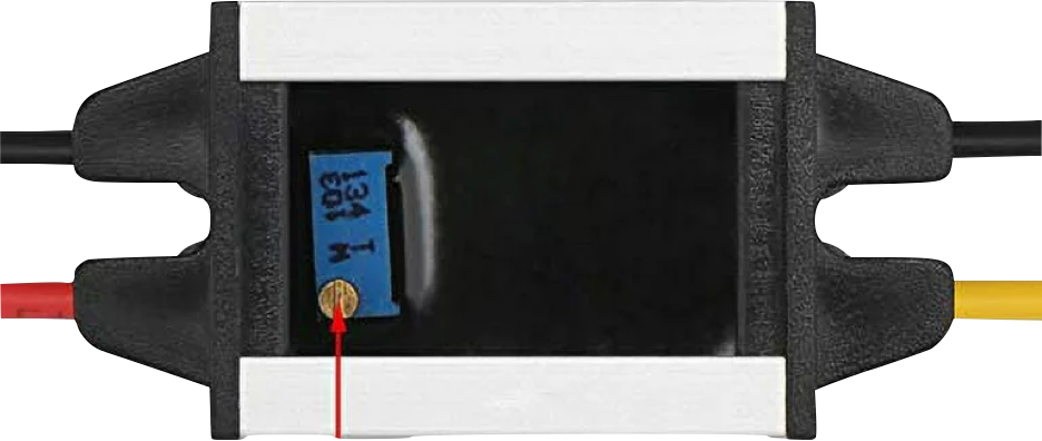
The DROK 18V to 5V step-down voltage converter is an efficient and reliable electronic component that converts a higher voltage level to a lower voltage level, specifically from 18 volts to a regulated 5 volts DC output. This component is commonly used in applications where electronic devices require a 5V power supply but are only available with an 18V source. Typical use cases include automotive electronics, battery-powered systems, and microcontroller-based projects, such as those involving an Arduino UNO.

Explore Projects Built with Stepdown 18v to 5V

Use Cirkit Designer to design, explore, and prototype these projects online. Some projects support real-time simulation. Click "Open Project" to start designing instantly!
Battery-Powered DC-DC Converter System for Multi-Voltage Power Distribution
Image of test 1 ih: A project utilizing Stepdown 18v to 5V in a practical application
This circuit converts a 38.5V battery output to multiple lower voltage levels using a series of DC-DC converters and a power module. It includes an emergency stop switch for safety and distributes power to various components such as a relay module, USB ports, and a bus servo adaptor.
Cirkit Designer LogoOpen Project in Cirkit Designer
12V to 5V Power Supply with LED Indicator and Push Switch
Image of Power Supply LVCO: A project utilizing Stepdown 18v to 5V in a practical application
This circuit is a 12V to 5V regulated power supply with an LED indicator. It uses a 5408 diode for reverse polarity protection, an LM340T5 7805 voltage regulator to step down the voltage to 5V, and a push switch to control the LED indicator. The circuit also includes capacitors for filtering and a resistor to limit the current through the LED.
Cirkit Designer LogoOpen Project in Cirkit Designer
USB Power Supply with Overcurrent Protection
Image of USB Charging port: A project utilizing Stepdown 18v to 5V in a practical application
This circuit is designed to step down voltage from a 12V battery to a lower voltage suitable for USB devices. It includes a buck converter connected to the battery through a fuse and fuse holder for overcurrent protection. The output of the buck converter is connected to a USB female port, providing a regulated power supply for USB-powered devices.
Cirkit Designer LogoOpen Project in Cirkit Designer
Battery-Powered UPS with Step-Down Buck Converter and BMS
Image of Mini ups: A project utilizing Stepdown 18v to 5V in a practical application
This circuit is a power management system that steps down a 240V AC input to a lower DC voltage using a buck converter, which then powers a 40W UPS. The UPS is controlled by a rocker switch and is backed up by a battery management system (BMS) connected to three 3.7V batteries in series, ensuring continuous power supply.
Cirkit Designer LogoOpen Project in Cirkit Designer

Explore Projects Built with Stepdown 18v to 5V

Use Cirkit Designer to design, explore, and prototype these projects online. Some projects support real-time simulation. Click "Open Project" to start designing instantly!
Image of test 1 ih: A project utilizing Stepdown 18v to 5V in a practical application
Battery-Powered DC-DC Converter System for Multi-Voltage Power Distribution
This circuit converts a 38.5V battery output to multiple lower voltage levels using a series of DC-DC converters and a power module. It includes an emergency stop switch for safety and distributes power to various components such as a relay module, USB ports, and a bus servo adaptor.
Cirkit Designer LogoOpen Project in Cirkit Designer
Image of Power Supply LVCO: A project utilizing Stepdown 18v to 5V in a practical application
12V to 5V Power Supply with LED Indicator and Push Switch
This circuit is a 12V to 5V regulated power supply with an LED indicator. It uses a 5408 diode for reverse polarity protection, an LM340T5 7805 voltage regulator to step down the voltage to 5V, and a push switch to control the LED indicator. The circuit also includes capacitors for filtering and a resistor to limit the current through the LED.
Cirkit Designer LogoOpen Project in Cirkit Designer
Image of USB Charging port: A project utilizing Stepdown 18v to 5V in a practical application
USB Power Supply with Overcurrent Protection
This circuit is designed to step down voltage from a 12V battery to a lower voltage suitable for USB devices. It includes a buck converter connected to the battery through a fuse and fuse holder for overcurrent protection. The output of the buck converter is connected to a USB female port, providing a regulated power supply for USB-powered devices.
Cirkit Designer LogoOpen Project in Cirkit Designer
Image of Mini ups: A project utilizing Stepdown 18v to 5V in a practical application
Battery-Powered UPS with Step-Down Buck Converter and BMS
This circuit is a power management system that steps down a 240V AC input to a lower DC voltage using a buck converter, which then powers a 40W UPS. The UPS is controlled by a rocker switch and is backed up by a battery management system (BMS) connected to three 3.7V batteries in series, ensuring continuous power supply.
Cirkit Designer LogoOpen Project in Cirkit Designer

Technical Specifications

Key Technical Details

  • Input Voltage Range: 6V to 20V DC
  • Output Voltage: 5V DC
  • Maximum Output Current: 3A
  • Conversion Efficiency: Up to 96%
  • Operating Temperature: -40°C to +85°C
  • Load Regulation: ± 0.5%
  • Voltage Regulation: ± 2.5%
  • Protection Features: Over-current, over-temperature, and short-circuit protection

Pin Configuration and Descriptions

Pin Number Name Description
1 VIN Input voltage (6V-20V DC)
2 GND Ground connection
3 VOUT Regulated 5V DC output
4 GND Ground connection for output

Usage Instructions

Integration into a Circuit

  1. Power Source Connection:

    • Connect the positive terminal of your 18V power source to the VIN pin of the step-down converter.
    • Connect the ground terminal of your power source to one of the GND pins on the input side of the converter.
  2. Load Connection:

    • Connect the positive terminal of your load (e.g., a microcontroller, sensor, or other electronic devices) to the VOUT pin.
    • Connect the ground terminal of your load to one of the GND pins on the output side of the converter.

Important Considerations and Best Practices

  • Heat Dissipation: Ensure adequate ventilation around the converter, as it may generate heat during operation.
  • Input Voltage: Do not exceed the maximum input voltage of 20V to prevent damage to the converter.
  • Output Current: Do not draw more than the maximum rated current of 3A from the output.
  • Wiring: Use appropriate gauge wires to handle the current without excessive voltage drop or overheating.

Troubleshooting and FAQs

Common Issues and Solutions

  • Output Voltage is Too Low or Unstable:

    • Check if the input voltage is within the specified range (6V-20V).
    • Ensure that the load does not exceed the maximum output current rating of 3A.
    • Verify that all connections are secure and free from corrosion or damage.
  • Converter is Overheating:

    • Reduce the load if it exceeds the converter's maximum current rating.
    • Improve airflow around the converter or add a heat sink if necessary.
  • No Output Voltage:

    • Check for proper input voltage and connections.
    • Inspect the converter for any signs of physical damage.
    • Ensure that the converter is not in a protection mode due to a short circuit or over-current condition.

FAQs

Q: Can I use this converter with an input voltage lower than 18V? A: Yes, the converter can accept an input voltage as low as 6V while still providing a regulated 5V output.

Q: Is it possible to adjust the output voltage? A: This particular model provides a fixed 5V output and does not support output voltage adjustment.

Q: How do I know if the converter is in protection mode? A: The converter may shut down output if it enters protection mode. Check for any conditions that may trigger protection, such as over-current, over-temperature, or short circuits.

Q: Can I use this converter with an Arduino UNO? A: Absolutely. The 5V output is suitable for powering an Arduino UNO or similar microcontroller boards that require a 5V supply.

Example Arduino UNO Connection

// No specific code is required for the step-down converter itself,
// as it is a hardware component. However, below is an example of
// how to connect the converter to an Arduino UNO for power supply.

// Arduino UNO Pin   Step-Down Converter Pin
// 5V               -> VOUT
// GND              -> GND (Output side)

// Remember to connect the 18V power source to the input side of the
// step-down converter. The Arduino can then be powered through its
// 5V and GND pins using the regulated output from the converter.

Please note that the above code is a wiring guide rather than executable code. The step-down converter does not require any software configuration and works independently once properly connected.