How to Use 4 CH Digital Logic Level Converter: Examples, Pinouts, and Specs
4 CH Digital Logic Level Converter Documentation
Manufacturer: Eletechsup
Part ID: OP71A04
1. Introduction
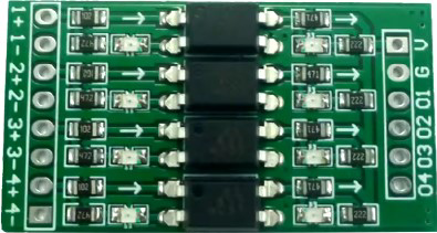
The 4 CH Digital Logic Level Converter (OP71A04) is a compact and versatile device designed to facilitate the conversion of digital signals between different voltage levels. It is commonly used to enable communication between components operating at incompatible logic levels, such as microcontrollers, sensors, and other peripherals.
This bidirectional level shifter supports both 3.3V and 5V logic levels, making it ideal for interfacing modern low-voltage devices with legacy systems or peripherals. With its four independent channels, the OP71A04 can handle multiple signals simultaneously, ensuring seamless integration in complex circuits.
Common Applications:
- Interfacing 3.3V microcontrollers (e.g., ESP32, Raspberry Pi) with 5V peripherals.
- Connecting 5V microcontrollers (e.g., Arduino UNO) to 3.3V sensors or modules.
- Bidirectional communication between devices with different voltage standards.
- I2C, SPI, UART, and GPIO signal level shifting.
2. Technical Specifications
Key Technical Details
| Parameter | Value |
|---|---|
| Operating Voltage (High) | 5V |
| Operating Voltage (Low) | 3.3V |
| Number of Channels | 4 |
| Bidirectional Support | Yes |
| Maximum Data Rate | 100 kHz (I2C) / 2 MHz (SPI, GPIO) |
| Dimensions | 15mm x 15mm x 3mm |
| Operating Temperature | -40°C to +85°C |
Pin Configuration and Descriptions
| Pin | Name | Description |
|---|---|---|
| 1 | HV | High Voltage Input (5V logic level) |
| 2 | LV | Low Voltage Input (3.3V logic level) |
| 3 | GND | Ground (common ground for both voltage levels) |
| 4 | TX1 | High-to-Low signal channel 1 (bidirectional) |
| 5 | TX2 | High-to-Low signal channel 2 (bidirectional) |
| 6 | TX3 | High-to-Low signal channel 3 (bidirectional) |
| 7 | TX4 | High-to-Low signal channel 4 (bidirectional) |
3. Usage Instructions
Connecting the Level Converter
Power Connections:
- Connect the HV pin to the 5V power supply of your high-voltage device (e.g., Arduino UNO).
- Connect the LV pin to the 3.3V power supply of your low-voltage device (e.g., ESP32).
- Connect the GND pin to the common ground shared by both devices.
Signal Connections:
- For each signal to be converted, connect the high-voltage side to the corresponding TXn pin on the HV side.
- Connect the low-voltage side to the corresponding TXn pin on the LV side.
- Repeat for all required channels (up to 4).
Example Circuit
Suppose you want to connect an Arduino UNO (5V logic) to an I2C sensor (3.3V logic).
- Connect the Arduino's 5V pin to the HV pin of the level converter.
- Connect the sensor's 3.3V pin to the LV pin of the level converter.
- Connect the Arduino's SCL and SDA pins to TX1 and TX2 on the HV side.
- Connect the sensor's SCL and SDA pins to TX1 and TX2 on the LV side.
Important Considerations:
- Ensure that the GND pin is connected to the common ground of all devices in the circuit.
- Do not exceed the maximum voltage ratings (5V for HV, 3.3V for LV).
- For high-speed communication (e.g., SPI), keep the wiring as short as possible to minimize signal degradation.
4. Arduino UNO Example Code
The following example demonstrates how to use the OP71A04 to interface an Arduino UNO with a 3.3V I2C sensor.
#include <Wire.h> // Include the Wire library for I2C communication

#define SENSOR_ADDRESS 0x40 // Replace with your sensor's I2C address

void setup() {
  Wire.begin(); // Initialize I2C communication
  Serial.begin(9600); // Start serial communication for debugging

  // Test communication with the sensor
  Wire.beginTransmission(SENSOR_ADDRESS);
  if (Wire.endTransmission() == 0) {
    Serial.println("Sensor detected successfully!");
  } else {
    Serial.println("Failed to detect sensor. Check connections.");
  }
}

void loop() {
  Wire.beginTransmission(SENSOR_ADDRESS);
  Wire.write(0x00); // Replace with the sensor's register address
  Wire.endTransmission();

  Wire.requestFrom(SENSOR_ADDRESS, 2); // Request 2 bytes of data
  if (Wire.available() == 2) {
    int data = Wire.read() << 8 | Wire.read(); // Combine two bytes into one value
    Serial.print("Sensor Data: ");
    Serial.println(data);
  } else {
    Serial.println("Failed to read data from sensor.");
  }

  delay(1000); // Wait 1 second before the next reading
}
Code Explanation:
- The
Wirelibrary is used to handle I2C communication. - The
Wire.begin()function initializes the I2C bus. - The
Wire.beginTransmission()andWire.endTransmission()functions are used to test communication with the sensor. - The
Wire.requestFrom()function retrieves data from the sensor.
5. Troubleshooting and FAQs
Common Issues and Solutions
| Issue | Solution |
|---|---|
| No communication between devices | Ensure proper power and ground connections. Verify voltage levels. |
| Data corruption or noise in signals | Use shorter wires and ensure proper grounding. |
| Sensor not detected in I2C communication | Check the sensor's I2C address and ensure pull-up resistors are present. |
| Overheating of the level converter | Verify that the input voltages do not exceed the specified limits. |
FAQs
Q1: Can I use this level converter for SPI communication?
Yes, the OP71A04 supports SPI communication. Ensure that the clock speed does not exceed 2 MHz for reliable operation.
Q2: Do I need external pull-up resistors for I2C communication?
Yes, external pull-up resistors (typically 4.7kΩ) are required on the SDA and SCL lines for proper I2C operation.
Q3: Can I use this converter for 1.8V to 3.3V level shifting?
No, the OP71A04 is designed specifically for 3.3V and 5V logic levels. For 1.8V applications, use a dedicated level shifter.
6. Conclusion
The Eletechsup OP71A04 4 CH Digital Logic Level Converter is an essential tool for interfacing devices with different logic levels. Its bidirectional functionality, compact design, and ease of use make it a reliable choice for a wide range of applications, from hobbyist projects to professional designs.
By following the guidelines and best practices outlined in this documentation, you can ensure seamless integration and optimal performance in your circuits.
Explore Projects Built with 4 CH Digital Logic Level Converter


Explore Projects Built with 4 CH Digital Logic Level Converter