How to Use ST7735: Examples, Pinouts, and Specs
Introduction
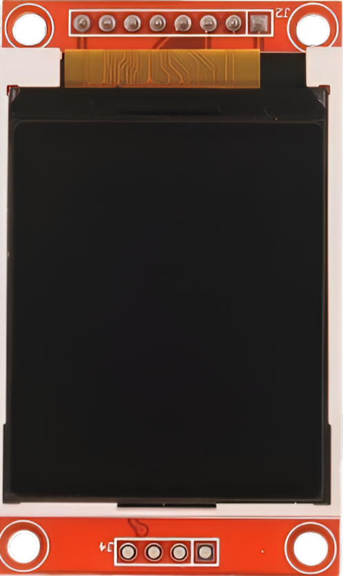
The ST7735 is a low-power, full-color LCD driver designed for small displays in embedded systems. It supports a variety of display resolutions and provides a simple interface for rendering graphics and text. This component is widely used in applications such as handheld devices, IoT displays, and portable instrumentation due to its compact size, low power consumption, and ease of integration.
Explore Projects Built with ST7735


Explore Projects Built with ST7735
Common Applications
- Handheld devices and portable electronics
- IoT devices with graphical interfaces
- Wearable technology
- Small instrumentation displays
- Educational and hobbyist projects (e.g., Arduino-based systems)
Technical Specifications
The ST7735 is a versatile LCD driver with the following key specifications:
| Parameter | Value |
|---|---|
| Operating Voltage | 2.8V to 3.3V |
| Interface Type | SPI (Serial Peripheral Interface) |
| Display Colors | 65K (16-bit RGB) or 262K (18-bit RGB) |
| Maximum Resolution | 132 x 162 pixels |
| Operating Temperature | -30°C to +85°C |
| Power Consumption | Low-power operation |
Pin Configuration
The ST7735 typically interfaces with a microcontroller through SPI. Below is the pin configuration for a common ST7735-based display module:
| Pin Name | Description |
|---|---|
| VCC | Power supply (2.8V to 3.3V) |
| GND | Ground |
| SCL (CLK) | Serial Clock (SPI clock input) |
| SDA (MOSI) | Serial Data (SPI data input) |
| RES (RST) | Reset pin (active low) |
| DC (A0) | Data/Command control pin |
| CS | Chip Select (active low) |
| LED | Backlight control (connect to power or PWM) |
Usage Instructions
Connecting the ST7735 to a Microcontroller
To use the ST7735, connect it to a microcontroller (e.g., Arduino UNO) via SPI. Below is a typical wiring configuration:
| ST7735 Pin | Arduino UNO Pin |
|---|---|
| VCC | 3.3V |
| GND | GND |
| SCL (CLK) | D13 (SCK) |
| SDA (MOSI) | D11 (MOSI) |
| RES (RST) | D8 |
| DC (A0) | D9 |
| CS | D10 |
| LED | 3.3V (or PWM pin) |
Example Code for Arduino UNO
Below is an example Arduino sketch to initialize and display graphics on the ST7735 using the Adafruit ST7735 library:
#include <Adafruit_GFX.h>    // Core graphics library
#include <Adafruit_ST7735.h> // ST7735 driver library
#include <SPI.h>             // SPI library

// Define pins for the ST7735
#define TFT_CS     10  // Chip select pin
#define TFT_RST    8   // Reset pin
#define TFT_DC     9   // Data/Command pin

// Initialize the ST7735 display
Adafruit_ST7735 tft = Adafruit_ST7735(TFT_CS, TFT_DC, TFT_RST);

void setup() {
  // Initialize the display
  tft.initR(INITR_BLACKTAB); // Use INITR_BLACKTAB for most ST7735 modules
  tft.setRotation(1);       // Set display orientation (0-3)
  tft.fillScreen(ST77XX_BLACK); // Clear the screen with black color

  // Display some text
  tft.setTextColor(ST77XX_WHITE); // Set text color to white
  tft.setTextSize(2);             // Set text size
  tft.setCursor(10, 10);          // Set text position
  tft.print("Hello, ST7735!");    // Print text to the display
}

void loop() {
  // Add any additional functionality here
}
Important Considerations
- Voltage Levels: Ensure the ST7735 operates at 3.3V. If using a 5V microcontroller, use level shifters for the SPI lines.
- Backlight Control: The LED pin can be connected to a PWM pin for brightness control or directly to 3.3V for full brightness.
- Library Compatibility: Use the Adafruit ST7735 library for easy integration. Install it via the Arduino Library Manager.
Troubleshooting and FAQs
Common Issues
No Display Output
- Cause: Incorrect wiring or power supply issues.
- Solution: Double-check all connections and ensure the VCC pin is supplied with 3.3V.
Flickering or Unstable Display
- Cause: SPI clock speed too high or poor connections.
- Solution: Lower the SPI clock speed in the library settings and ensure secure connections.
Inverted Colors
- Cause: Incorrect initialization settings.
- Solution: Use the correct initialization command (e.g.,
INITR_BLACKTAB).
Backlight Not Working
- Cause: LED pin not connected or insufficient power.
- Solution: Connect the LED pin to 3.3V or a PWM pin for brightness control.
FAQs
Can the ST7735 work with 5V microcontrollers?
- Yes, but you must use level shifters for the SPI lines to avoid damaging the display.
What is the maximum resolution supported?
- The ST7735 supports a maximum resolution of 132 x 162 pixels.
Can I use the ST7735 with platforms other than Arduino?
- Yes, the ST7735 can be used with other platforms like Raspberry Pi, ESP32, and STM32, provided the SPI interface is configured correctly.
How do I control the brightness of the display?
- Connect the LED pin to a PWM-capable pin on your microcontroller and use PWM signals to adjust brightness.
By following this documentation, you can successfully integrate the ST7735 into your projects and troubleshoot common issues effectively.