How to Use LM2596 MultiChannel: Examples, Pinouts, and Specs
Introduction
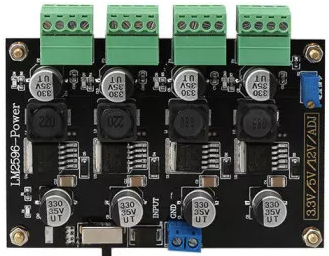
The LM2596 MultiChannel (Manufacturer Part ID: LM2596-X4) is a step-down (buck) voltage regulator manufactured by Shopee. It is designed to efficiently convert a higher input voltage to a lower output voltage, supporting multiple output channels. This component is ideal for applications requiring adjustable output voltage and high current capability, such as power supply circuits, battery chargers, and embedded systems.
Explore Projects Built with LM2596 MultiChannel


Explore Projects Built with LM2596 MultiChannel
Common Applications:
- Multi-output power supply circuits
- Battery charging systems
- Voltage regulation in embedded systems
- LED drivers
- Industrial automation equipment
Technical Specifications
Key Technical Details:
- Input Voltage Range: 4.5V to 40V
- Output Voltage Range: 1.23V to 37V (adjustable)
- Output Current: Up to 3A per channel
- Efficiency: Up to 92%
- Switching Frequency: 150 kHz (fixed)
- Thermal Shutdown Protection: Yes
- Short Circuit Protection: Yes
- Number of Channels: 4 (independent outputs)
- Package Type: Multi-channel module with screw terminals and potentiometers
Pin Configuration and Descriptions:
The LM2596 MultiChannel module has multiple input and output terminals for each channel. Below is the pin configuration:
Input/Output Terminals:
| Pin Name | Description |
|---|---|
| VIN+ | Positive input voltage terminal |
| VIN- | Negative input voltage terminal (GND) |
| VOUT+ (CH1) | Positive output voltage for Channel 1 |
| VOUT- (CH1) | Negative output voltage for Channel 1 |
| VOUT+ (CH2) | Positive output voltage for Channel 2 |
| VOUT- (CH2) | Negative output voltage for Channel 2 |
| VOUT+ (CH3) | Positive output voltage for Channel 3 |
| VOUT- (CH3) | Negative output voltage for Channel 3 |
| VOUT+ (CH4) | Positive output voltage for Channel 4 |
| VOUT- (CH4) | Negative output voltage for Channel 4 |
Adjustment Potentiometers:
| Component | Description |
|---|---|
| POT1 | Adjusts output voltage for Channel 1 |
| POT2 | Adjusts output voltage for Channel 2 |
| POT3 | Adjusts output voltage for Channel 3 |
| POT4 | Adjusts output voltage for Channel 4 |
Usage Instructions
How to Use the LM2596 MultiChannel in a Circuit:
Connect Input Voltage:
- Connect the positive input voltage to the
VIN+terminal. - Connect the ground (negative input voltage) to the
VIN-terminal. - Ensure the input voltage is within the range of 4.5V to 40V.
- Connect the positive input voltage to the
Connect Output Load:
- For each channel, connect the load to the corresponding
VOUT+andVOUT-terminals. - Ensure the load does not exceed the maximum current rating of 3A per channel.
- For each channel, connect the load to the corresponding
Adjust Output Voltage:
- Use the potentiometers (POT1 to POT4) to adjust the output voltage for each channel.
- Measure the output voltage using a multimeter while adjusting the potentiometer.
Power On:
- Once all connections are secure, power on the module by supplying the input voltage.
Important Considerations:
- Heat Dissipation: The LM2596 MultiChannel module may generate heat during operation. Ensure proper ventilation or use a heatsink if necessary.
- Input Voltage: Always ensure the input voltage is higher than the desired output voltage by at least 1.5V for proper regulation.
- Load Current: Do not exceed the maximum current rating of 3A per channel to avoid damage.
- Polarity: Double-check the polarity of the input and output connections to prevent damage to the module.
Example: Using LM2596 MultiChannel with Arduino UNO
The LM2596 MultiChannel can be used to power an Arduino UNO and other peripherals. Below is an example of how to connect and use it:
Circuit Setup:
- Connect a 12V DC power supply to the
VIN+andVIN-terminals. - Adjust the output voltage of Channel 1 to 5V using POT1.
- Connect the
VOUT+andVOUT-of Channel 1 to the Arduino UNO'sVINandGNDpins, respectively. - Use the remaining channels to power other peripherals, such as sensors or motors.
Arduino Code Example:
// Example code to read a sensor powered by LM2596 MultiChannel
// Channel 1 powers the Arduino UNO (5V), and Channel 2 powers the sensor (3.3V)

const int sensorPin = A0; // Analog pin connected to the sensor output
int sensorValue = 0;      // Variable to store the sensor reading

void setup() {
  Serial.begin(9600); // Initialize serial communication
  pinMode(sensorPin, INPUT); // Set the sensor pin as input
}

void loop() {
  sensorValue = analogRead(sensorPin); // Read the sensor value
  Serial.print("Sensor Value: ");
  Serial.println(sensorValue); // Print the sensor value to the Serial Monitor
  delay(1000); // Wait for 1 second before the next reading
}
Troubleshooting and FAQs
Common Issues and Solutions:
No Output Voltage:
- Cause: Incorrect input connections or insufficient input voltage.
- Solution: Verify the input voltage is within the specified range and check the polarity of the connections.
Output Voltage Not Adjustable:
- Cause: Faulty potentiometer or incorrect adjustment.
- Solution: Ensure the potentiometer is functional and adjust it slowly while monitoring the output voltage.
Overheating:
- Cause: Excessive load current or poor ventilation.
- Solution: Reduce the load current or add a heatsink to improve heat dissipation.
Short Circuit Protection Triggered:
- Cause: Output terminals are shorted.
- Solution: Disconnect the load, check for shorts, and reconnect properly.
FAQs:
Q: Can I use the LM2596 MultiChannel to power multiple devices with different voltage requirements?
- A: Yes, each channel can be adjusted independently to provide different output voltages.
Q: What is the maximum power output of the module?
- A: The maximum power output depends on the input voltage and current, but each channel can deliver up to 3A.
Q: Can I use this module with a battery as the input source?
- A: Yes, as long as the battery voltage is within the input voltage range (4.5V to 40V).
Q: Is the module protected against reverse polarity?
- A: No, the module does not have built-in reverse polarity protection. Ensure correct polarity to avoid damage.