How to Use USB Plug: Examples, Pinouts, and Specs
Introduction
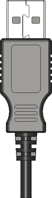
A USB plug is a standardized connector used to connect devices to a power source or to transfer data between devices. It is an essential component in modern electronics, enabling seamless communication and power delivery. USB plugs come in various types, including USB-A, USB-B, and USB-C, each designed for specific applications such as charging mobile devices, connecting peripherals, or transferring data between computers and external devices.
Explore Projects Built with USB Plug

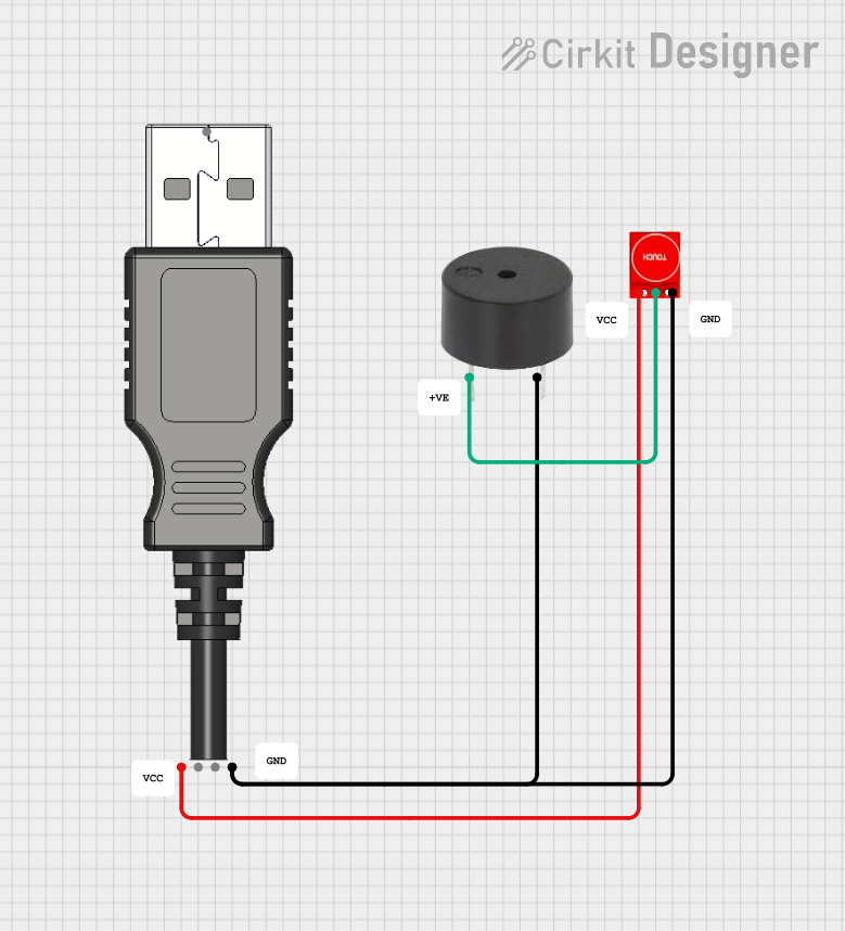


Explore Projects Built with USB Plug
Common Applications and Use Cases
- Charging smartphones, tablets, and other portable devices
- Connecting peripherals like keyboards, mice, and printers to computers
- Data transfer between storage devices and computers
- Powering small electronic devices such as microcontrollers and development boards
- Audio and video transmission in modern USB-C implementations
Technical Specifications
General Specifications
- Voltage Rating: 5V (standard), up to 20V for USB-C Power Delivery
- Current Rating:
- USB 2.0: Up to 500mA
- USB 3.0: Up to 900mA
- USB-C: Up to 5A (with Power Delivery)
- Data Transfer Speeds:
- USB 2.0: Up to 480 Mbps
- USB 3.0: Up to 5 Gbps
- USB 3.1/3.2: Up to 10 Gbps
- USB4: Up to 40 Gbps
- Connector Types: USB-A, USB-B, USB-C, Mini-USB, Micro-USB
- Durability: Rated for 1,500 to 10,000 insertion/removal cycles depending on the type
Pin Configuration and Descriptions
USB-A Plug
| Pin Number | Name | Description |
|---|---|---|
| 1 | VBUS | +5V Power |
| 2 | D- | Data Line (negative) |
| 3 | D+ | Data Line (positive) |
| 4 | GND | Ground |
USB-C Plug
| Pin Number | Name | Description |
|---|---|---|
| A1, B1 | GND | Ground |
| A2, B2 | TX1+ | SuperSpeed Differential Pair 1 (positive) |
| A3, B3 | TX1- | SuperSpeed Differential Pair 1 (negative) |
| A4, B4 | VBUS | +5V to +20V Power |
| A5, B5 | CC1, CC2 | Configuration Channel |
| A6, B6 | D+ | USB 2.0 Data Line (positive) |
| A7, B7 | D- | USB 2.0 Data Line (negative) |
| A8, B8 | SBU1, SBU2 | Sideband Use |
| A9, B9 | RX2- | SuperSpeed Differential Pair 2 (negative) |
| A10, B10 | RX2+ | SuperSpeed Differential Pair 2 (positive) |
Usage Instructions
How to Use the USB Plug in a Circuit
- Identify the Type of USB Plug: Determine whether you need USB-A, USB-B, or USB-C based on your application.
- Connect Power and Ground:
- For USB-A and USB-B, connect the VBUS pin to a 5V power source and the GND pin to ground.
- For USB-C, ensure proper configuration of the VBUS and GND pins, and use the CC pins for negotiation if required.
- Data Lines: Connect the D+ and D- pins to the corresponding data lines of your device for data transfer.
- Use Proper Resistors for USB-C: If using USB-C, include pull-up or pull-down resistors on the CC pins to indicate the power role (source or sink).
- Secure the Connection: Use a proper USB socket or solder the plug securely to avoid loose connections.
Important Considerations and Best Practices
- Voltage and Current Ratings: Ensure the power source matches the voltage and current requirements of your device.
- Cable Quality: Use high-quality USB cables to minimize resistance and ensure reliable data transfer.
- USB-C Power Delivery: For USB-C, use a compatible controller or IC to handle power delivery negotiation.
- Avoid Overloading: Do not exceed the current rating of the USB plug to prevent overheating or damage.
- ESD Protection: Include electrostatic discharge (ESD) protection diodes on the data lines for sensitive devices.
Example: Connecting a USB Plug to an Arduino UNO
To power an Arduino UNO using a USB plug, connect the USB-A plug to a 5V USB power source and plug the other end into the Arduino's USB port. If you are using a USB-C plug, ensure proper wiring of the VBUS and GND pins.
Example Code for Serial Communication via USB
// This code demonstrates serial communication between an Arduino UNO
// and a computer via a USB connection.

void setup() {
  Serial.begin(9600); // Initialize serial communication at 9600 baud
  while (!Serial) {
    // Wait for the serial port to connect (for Leonardo/Micro boards)
  }
  Serial.println("USB Communication Initialized");
}

void loop() {
  if (Serial.available() > 0) {
    // Read incoming data from the USB serial connection
    char received = Serial.read();
    Serial.print("Received: ");
    Serial.println(received); // Echo the received character
  }
}
Troubleshooting and FAQs
Common Issues
USB Plug Not Recognized by Device
- Cause: Loose connection or damaged cable.
- Solution: Check the connection and replace the cable if necessary.
Device Not Charging
- Cause: Insufficient current from the power source.
- Solution: Use a power source with a higher current rating or a USB-C plug with Power Delivery.
Data Transfer Fails
- Cause: Incorrect wiring of data lines or poor cable quality.
- Solution: Verify the D+ and D- connections and use a high-quality cable.
Overheating
- Cause: Exceeding the current rating of the USB plug.
- Solution: Reduce the load or use a USB plug with a higher current rating.
FAQs
Q: Can I use a USB-C plug with older USB devices?
- A: Yes, but you will need an adapter or a cable with USB-C on one end and the appropriate connector on the other.
Q: How do I identify the pinout of a USB plug?
- A: Refer to the pin configuration tables provided above or use a multimeter to trace the connections.
Q: Is it safe to use a USB plug for high-power devices?
- A: Only if the USB plug and cable are rated for the required voltage and current. Use USB-C with Power Delivery for high-power applications.