
How to Use Mini-USB _B_ connector with 5th pin broken out.: Examples, Pinouts, and Specs
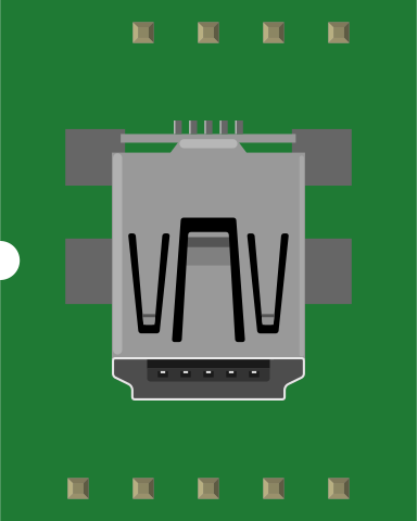
 Design with Mini-USB _B_ connector with 5th pin broken out. in Cirkit Designer
Introduction
The Mini-USB B connector is a compact USB interface commonly used in devices such as digital cameras, older mobile phones, and portable electronics. It is designed for data transfer and power supply in small devices. This specific version of the Mini-USB B connector features a 5th pin that is broken out, enabling additional functionality, such as custom configurations for data communication or power delivery.
Explore Projects Built with Mini-USB _B_ connector with 5th pin broken out.
 Open Project in Cirkit Designer
 Open Project in Cirkit Designer
 Open Project in Cirkit Designer
 Open Project in Cirkit Designer
Explore Projects Built with Mini-USB _B_ connector with 5th pin broken out.
Open Project in Cirkit DesignerOpen Project in Cirkit DesignerOpen Project in Cirkit DesignerOpen Project in Cirkit DesignerCommon Applications and Use Cases
- Connecting portable devices to computers for data transfer
- Charging small electronic devices
- Custom circuits requiring USB communication with additional functionality
- Prototyping projects that require access to the 5th pin for advanced configurations
Technical Specifications
Key Technical Details
- Connector Type: Mini-USB B
- Number of Pins: 5 (including the broken-out 5th pin)
- Voltage Rating: 5V DC (standard USB voltage)
- Current Rating: Up to 1.8A (depending on the cable and device)
- Mounting Type: Through-hole or surface-mount (varies by model)
- Durability: Rated for 5,000 insertion/removal cycles
- Operating Temperature: -20°C to 85°C
Pin Configuration and Descriptions
The Mini-USB B connector has five pins, with the 5th pin (ID pin) broken out for additional functionality. Below is the pinout:
| Pin Number | Name | Description |
|---|---|---|
| 1 | VBUS | Power supply (5V DC) |
| 2 | D- | Data line (negative) |
| 3 | D+ | Data line (positive) |
| 4 | ID | Identification pin (broken out for custom use, e.g., OTG or mode selection) |
| 5 | GND | Ground |
Usage Instructions
How to Use the Component in a Circuit
Mounting the Connector:
- Solder the Mini-USB B connector onto a PCB using the through-hole or surface-mount pads.
- Ensure proper alignment of the pins to avoid short circuits.
Connecting the Pins:
- Connect Pin 1 (VBUS) to the 5V power supply line.
- Connect Pin 5 (GND) to the ground of your circuit.
- Use Pins 2 (D-) and 3 (D+) for data communication.
- Utilize Pin 4 (ID) for custom configurations, such as enabling USB On-The-Go (OTG) functionality or mode selection.
Example Circuit:
- For a basic USB-powered device, connect VBUS and GND to power the circuit, and use D+ and D- for data transfer.
- If using the ID pin, connect it to a microcontroller GPIO pin or use it to toggle between host and device modes.
Important Considerations and Best Practices
- Avoid Overloading: Ensure the connected device does not draw more current than the USB port or power source can supply.
- Proper Soldering: Use appropriate soldering techniques to avoid damaging the connector or PCB.
- Shielding: For high-speed data transfer, use a shielded USB cable to minimize interference.
- ID Pin Usage: The ID pin can be left unconnected if not required, but breaking it out allows for advanced configurations.
Arduino UNO Example Code
If you are using the Mini-USB B connector with an Arduino UNO for data communication, here is an example code snippet:
/* Example: Reading data from a USB-connected device via Mini-USB B connector
   Ensure the D+ and D- lines are connected to appropriate USB-to-serial
   converter or microcontroller pins for communication. */

#include <SoftwareSerial.h>

// Define RX and TX pins for USB-to-serial communication
SoftwareSerial usbSerial(10, 11); // RX = Pin 10, TX = Pin 11

void setup() {
  Serial.begin(9600); // Initialize serial monitor
  usbSerial.begin(9600); // Initialize USB communication

  Serial.println("Mini-USB B Connector Test");
}

void loop() {
  // Check if data is available from the USB device
  if (usbSerial.available()) {
    char data = usbSerial.read(); // Read data from USB
    Serial.print("Received: ");
    Serial.println(data); // Print received data to serial monitor
  }

  // Send data to USB device
  usbSerial.println("Hello from Arduino!");
  delay(1000); // Wait 1 second before sending again
}
Troubleshooting and FAQs
Common Issues Users Might Face
No Power to the Device:
- Cause: Incorrect connection of VBUS or GND pins.
- Solution: Verify the soldering and ensure proper connections to the power supply.
Data Transfer Fails:
- Cause: Misaligned or loose D+ and D- connections.
- Solution: Check the solder joints and ensure the USB cable is securely connected.
ID Pin Not Functioning:
- Cause: ID pin not connected or configured correctly.
- Solution: Verify the circuit design and ensure the ID pin is connected to the intended GPIO or configuration circuit.
Overheating:
- Cause: Excessive current draw or short circuit.
- Solution: Check the circuit for shorts and ensure the connected device does not exceed the current rating.
Solutions and Tips for Troubleshooting
- Use a multimeter to check continuity and voltage levels on each pin.
- Test the connector with a known working USB cable and device to isolate issues.
- If using the ID pin, consult the device's datasheet or USB OTG specifications for proper configuration.
By following this documentation, you can effectively integrate and troubleshoot the Mini-USB B connector with the 5th pin broken out in your projects.