How to Use sensor_biometrico_398f7dc151bf6f3c243cdd2da7229a70_1_schematic: Examples, Pinouts, and Specs
Introduction
The Sensor_Biometrico_398f7dc151bf6f3c243cdd2da7229a70_1_Schematic is a biometric sensor designed to capture and analyze biological data, such as fingerprints or facial features, for authentication and identification purposes. This sensor is widely used in security systems, access control devices, and personal electronics to enhance security and provide seamless user authentication.
Explore Projects Built with sensor_biometrico_398f7dc151bf6f3c243cdd2da7229a70_1_schematic
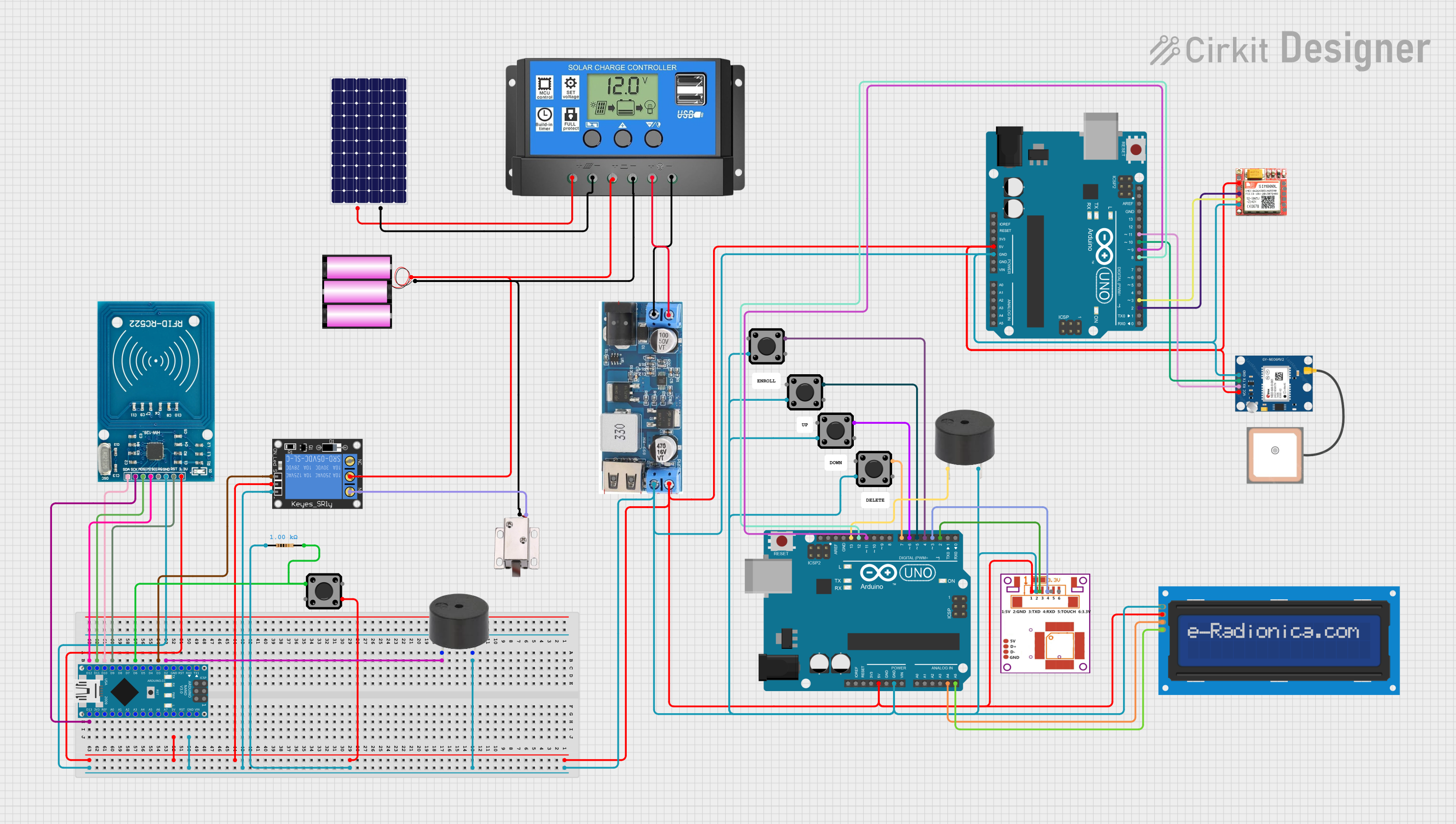

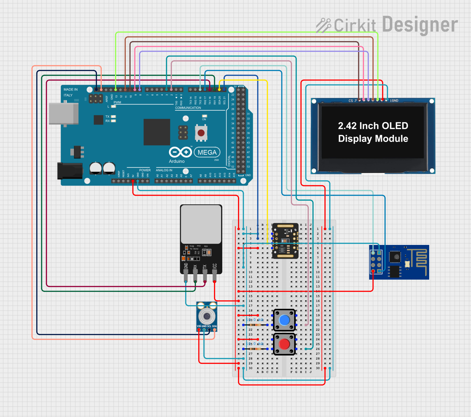
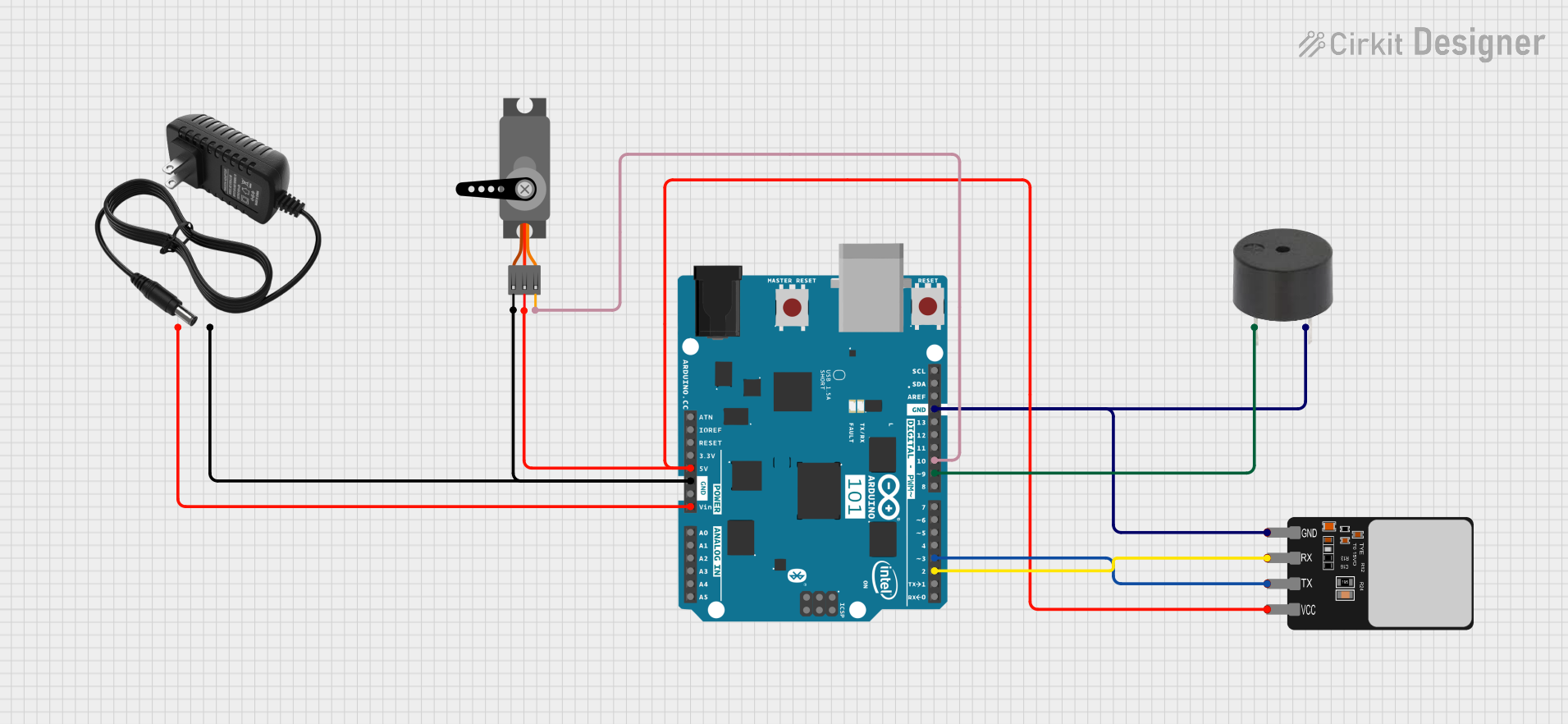
Explore Projects Built with sensor_biometrico_398f7dc151bf6f3c243cdd2da7229a70_1_schematic
Common Applications and Use Cases
- Access Control Systems: Used in doors, safes, and restricted areas for secure entry.
- Consumer Electronics: Integrated into smartphones, laptops, and tablets for user authentication.
- Time and Attendance Systems: Tracks employee attendance using biometric data.
- Banking and Payment Systems: Provides secure authentication for transactions.
- Healthcare Devices: Monitors and authenticates patients using biometric data.
Technical Specifications
The following table outlines the key technical details of the sensor:
| Parameter | Value |
|---|---|
| Operating Voltage | 3.3V to 5V |
| Operating Current | 50mA (typical), 80mA (maximum) |
| Communication Protocol | UART (9600 bps default) |
| Sensor Type | Optical or Capacitive (varies) |
| Resolution | 500 DPI |
| Storage Capacity | Up to 200 fingerprints |
| Operating Temperature | -20°C to 60°C |
| Dimensions | 32mm x 20mm x 10mm |
Pin Configuration and Descriptions
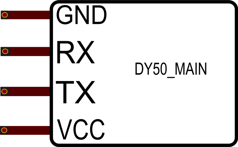
The sensor has a 6-pin interface. The pin configuration is as follows:
| Pin | Name | Description |
|---|---|---|
| 1 | VCC | Power supply input (3.3V to 5V). |
| 2 | GND | Ground connection. |
| 3 | TX | UART Transmit pin (sends data to the microcontroller). |
| 4 | RX | UART Receive pin (receives data from the microcontroller). |
| 5 | EN | Enable pin (active HIGH to power on the sensor). |
| 6 | RST | Reset pin (active LOW to reset the sensor). |
Usage Instructions
How to Use the Component in a Circuit
- Power the Sensor: Connect the VCC pin to a 3.3V or 5V power source and the GND pin to ground.
- Connect UART Pins: Connect the TX pin of the sensor to the RX pin of the microcontroller and the RX pin of the sensor to the TX pin of the microcontroller.
- Enable the Sensor: Set the EN pin HIGH to activate the sensor.
- Optional Reset: Use the RST pin to reset the sensor if needed.
- Communication: Use UART communication to send commands and receive data from the sensor.
Important Considerations and Best Practices
- Ensure the power supply is stable and within the specified voltage range to avoid damage.
- Use a level shifter if interfacing with a 3.3V microcontroller while powering the sensor at 5V.
- Avoid exposing the sensor to direct sunlight or extreme temperatures for accurate readings.
- Clean the sensor surface regularly to maintain optimal performance.
- Use proper UART settings (9600 bps, 8 data bits, no parity, 1 stop bit) for communication.
Example Code for Arduino UNO
Below is an example code snippet to interface the sensor with an Arduino UNO:
#include <SoftwareSerial.h>

// Define RX and TX pins for the sensor
SoftwareSerial biometricSensor(2, 3); // RX = Pin 2, TX = Pin 3

void setup() {
  Serial.begin(9600); // Initialize Serial Monitor
  biometricSensor.begin(9600); // Initialize UART communication with the sensor

  Serial.println("Initializing Biometric Sensor...");
  delay(1000);

  // Example command to check sensor connection
  biometricSensor.write(0x55); // Send a dummy command to the sensor
  delay(100);

  if (biometricSensor.available()) {
    Serial.println("Sensor is connected and responding.");
  } else {
    Serial.println("Failed to connect to the sensor.");
  }
}

void loop() {
  // Example: Continuously read data from the sensor
  if (biometricSensor.available()) {
    char data = biometricSensor.read();
    Serial.print("Sensor Data: ");
    Serial.println(data);
  }
}
Notes:
- Replace
0x55with the actual command for your specific sensor model. - Ensure the RX and TX pins are correctly connected to the Arduino.
Troubleshooting and FAQs
Common Issues and Solutions
Sensor Not Responding:
- Cause: Incorrect wiring or power supply issues.
- Solution: Double-check the connections and ensure the power supply is stable.
Data Transmission Errors:
- Cause: Mismatched UART settings.
- Solution: Verify the baud rate and UART configuration.
Inaccurate Readings:
- Cause: Dirty sensor surface or environmental interference.
- Solution: Clean the sensor and avoid direct sunlight or extreme temperatures.
Sensor Fails to Initialize:
- Cause: EN pin not set HIGH or RST pin held LOW.
- Solution: Ensure the EN pin is HIGH and the RST pin is not held LOW.
FAQs
Q: Can this sensor store multiple fingerprints?
- A: Yes, it can store up to 200 fingerprints in its internal memory.
Q: Is it compatible with 3.3V microcontrollers?
- A: Yes, but ensure the power supply matches the microcontroller voltage or use a level shifter.
Q: How do I reset the sensor?
- A: Pull the RST pin LOW momentarily to reset the sensor.
Q: Can it be used outdoors?
- A: It is not recommended for outdoor use due to potential environmental interference.
This concludes the documentation for the Sensor_Biometrico_398f7dc151bf6f3c243cdd2da7229a70_1_Schematic.