
How to Use 2 Channel 5V Relay Module ESP 32: Examples, Pinouts, and Specs
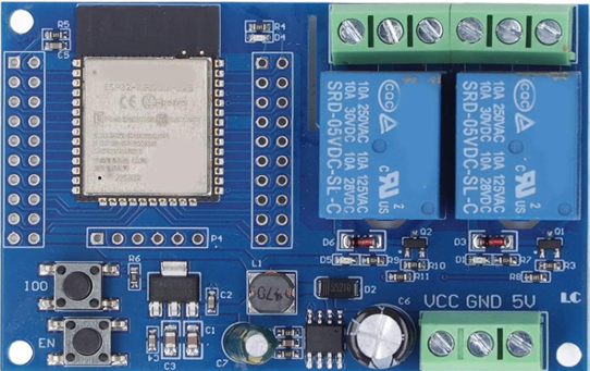
 Design with 2 Channel 5V Relay Module ESP 32 in Cirkit Designer
Introduction
The 2 Channel 5V Relay Module ESP32, manufactured by Espressif, is a versatile electronic component designed for controlling high-power devices such as lights, fans, and appliances. It integrates seamlessly with the ESP32 microcontroller, enabling wireless control via Wi-Fi or Bluetooth. This module is ideal for home automation, IoT projects, and industrial control systems.
Common applications include:
- Smart home automation (e.g., controlling lights or appliances remotely)
- Industrial equipment control
- IoT-based switching systems
- Prototyping and educational projects
Explore Projects Built with 2 Channel 5V Relay Module ESP 32
 Open Project in Cirkit Designer
 Open Project in Cirkit Designer
 Open Project in Cirkit Designer
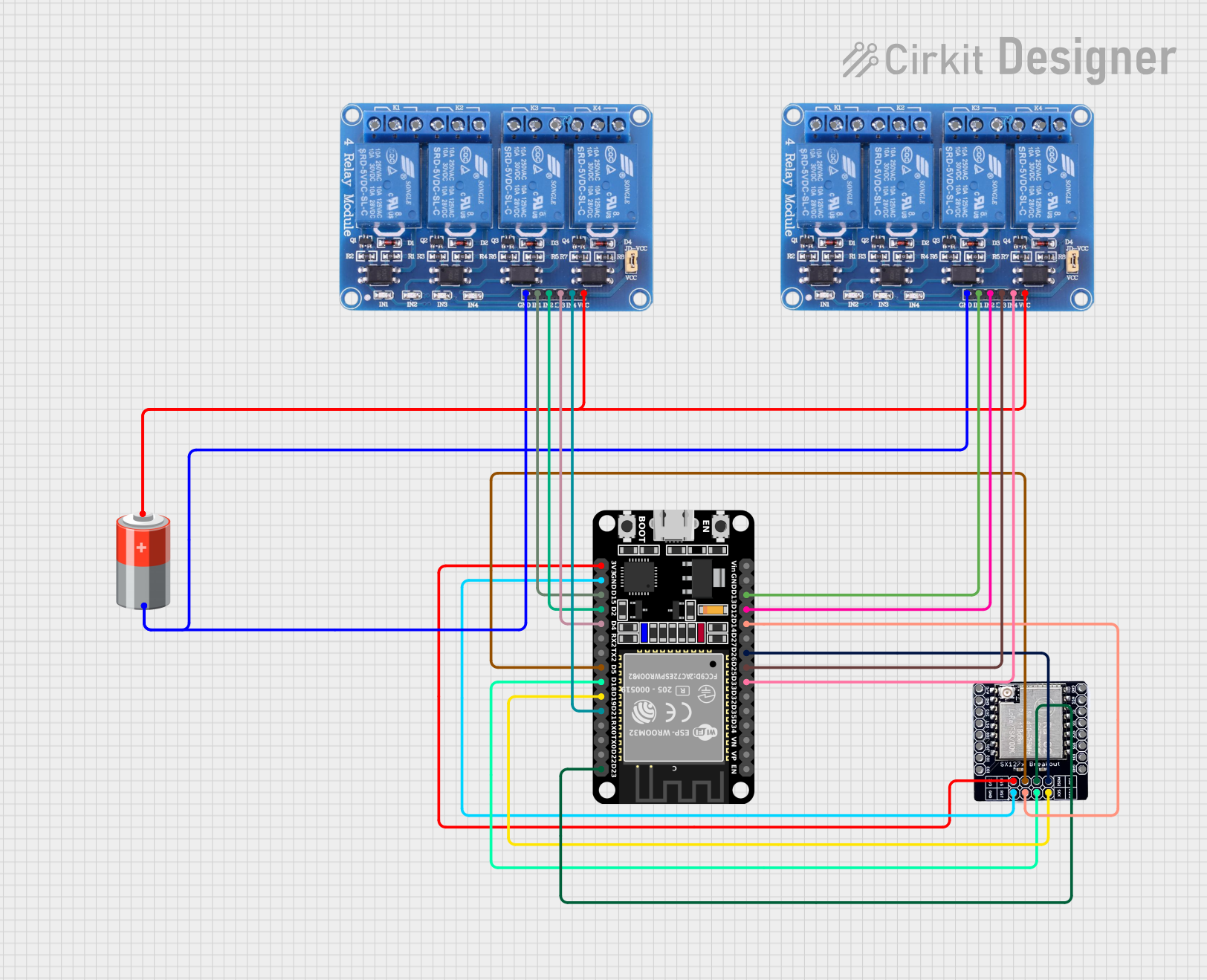 Open Project in Cirkit Designer
Explore Projects Built with 2 Channel 5V Relay Module ESP 32
Open Project in Cirkit DesignerOpen Project in Cirkit DesignerOpen Project in Cirkit DesignerOpen Project in Cirkit DesignerTechnical Specifications
The following are the key technical details of the 2 Channel 5V Relay Module ESP32:
General Specifications
- Operating Voltage: 5V DC
- Relay Channels: 2
- Control Signal Voltage: 3.3V (compatible with ESP32 GPIO pins)
- Maximum Load (per channel):
- AC: 250V at 10A
- DC: 30V at 10A
- Trigger Mode: Active low
- Isolation: Optocoupler isolation for safe operation
- Dimensions: 50mm x 40mm x 18mm (approx.)
Pin Configuration and Descriptions
The module has two main interfaces: the input control pins and the relay output terminals.
Input Control Pins
| Pin Name | Description |
|---|---|
| VCC | Connect to 5V power supply |
| GND | Ground connection |
| IN1 | Control signal for Relay 1 (active low) |
| IN2 | Control signal for Relay 2 (active low) |
Relay Output Terminals (per channel)
| Terminal | Description |
|---|---|
| COM | Common terminal for the relay |
| NO | Normally Open terminal (connected to COM when active) |
| NC | Normally Closed terminal (connected to COM when idle) |
Usage Instructions
Connecting the Module to an ESP32
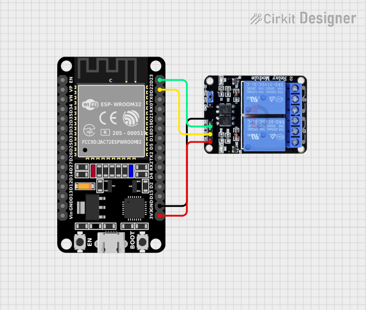
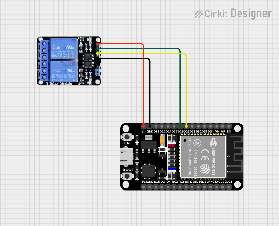
- Power the Module: Connect the VCC pin of the relay module to the 5V pin of the ESP32 and the GND pin to the ESP32's GND.
- Control Pins: Connect the IN1 and IN2 pins to two GPIO pins on the ESP32 (e.g., GPIO 26 and GPIO 27).
- Relay Outputs: Wire the devices you want to control to the relay output terminals (COM, NO, NC) as per your requirements.
Example Circuit
- Relay 1: Connect a light bulb to the NO terminal of Relay 1, and the other end to the power source. Connect the COM terminal to the neutral line.
- Relay 2: Similarly, connect another device to Relay 2's terminals.
Example Code for ESP32
Below is an example Arduino sketch to control the relay module using an ESP32:
// Define GPIO pins for the relay control signals
#define RELAY1_PIN 26  // GPIO pin connected to IN1
#define RELAY2_PIN 27  // GPIO pin connected to IN2

void setup() {
  // Initialize serial communication for debugging
  Serial.begin(115200);

  // Set relay pins as outputs
  pinMode(RELAY1_PIN, OUTPUT);
  pinMode(RELAY2_PIN, OUTPUT);

  // Ensure relays are off at startup
  digitalWrite(RELAY1_PIN, HIGH); // Active low, so HIGH turns it off
  digitalWrite(RELAY2_PIN, HIGH); // Active low, so HIGH turns it off
}

void loop() {
  // Turn on Relay 1
  Serial.println("Turning on Relay 1...");
  digitalWrite(RELAY1_PIN, LOW); // Active low, so LOW turns it on
  delay(2000); // Wait for 2 seconds

  // Turn off Relay 1 and turn on Relay 2
  Serial.println("Turning off Relay 1 and turning on Relay 2...");
  digitalWrite(RELAY1_PIN, HIGH); // Turn off Relay 1
  digitalWrite(RELAY2_PIN, LOW);  // Turn on Relay 2
  delay(2000); // Wait for 2 seconds

  // Turn off both relays
  Serial.println("Turning off both relays...");
  digitalWrite(RELAY1_PIN, HIGH);
  digitalWrite(RELAY2_PIN, HIGH);
  delay(2000); // Wait for 2 seconds
}
Important Considerations
- Power Supply: Ensure the module is powered with a stable 5V DC supply. Using an unstable power source may cause erratic behavior.
- Isolation: The module uses optocouplers for isolation, but additional precautions should be taken when working with high voltages.
- GPIO Voltage Compatibility: The module is designed to work with 3.3V control signals, making it fully compatible with the ESP32.
Troubleshooting and FAQs
Common Issues
Relays not switching:
- Ensure the VCC and GND connections are secure.
- Verify that the control signals (IN1, IN2) are being correctly toggled by the ESP32.
- Check if the power supply is providing sufficient current.
Relay clicks but no output:
- Double-check the wiring of the relay output terminals (COM, NO, NC).
- Ensure the load connected to the relay is within the specified voltage and current ratings.
ESP32 resets when relay is activated:
- This may occur due to insufficient power supply. Use a separate 5V power source for the relay module.
FAQs
Q: Can I use this module with a 12V power supply?
A: No, this module is designed to operate at 5V DC. Using a higher voltage may damage the module.
Q: Is it safe to control AC appliances with this module?
A: Yes, but ensure proper insulation and follow safety guidelines when working with high voltages.
Q: Can I control the relays via Wi-Fi or Bluetooth?
A: Yes, the ESP32 can be programmed to receive commands over Wi-Fi or Bluetooth and control the relays accordingly.
Q: What is the maximum switching frequency of the relays?
A: Mechanical relays are not designed for high-frequency switching. For most applications, a switching frequency of 1Hz or lower is recommended.
By following this documentation, you can effectively integrate and use the 2 Channel 5V Relay Module ESP32 in your projects.