
How to Use Adafruit CAN Bus FeatherWing: Examples, Pinouts, and Specs
 Design with Adafruit CAN Bus FeatherWing in Cirkit Designer
Introduction
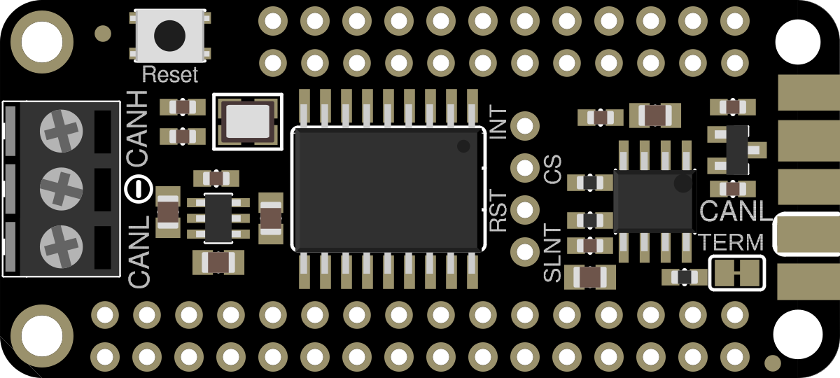
The Adafruit CAN Bus FeatherWing (Manufacturer Part ID: 5709) is a versatile add-on board designed for Feather microcontrollers. It enables communication over the Controller Area Network (CAN) protocol, which is widely used in automotive, industrial, and embedded systems. This FeatherWing simplifies the process of adding CAN bus functionality to your projects, making it ideal for applications such as vehicle diagnostics, industrial automation, and robotics.
Explore Projects Built with Adafruit CAN Bus FeatherWing
 Open Project in Cirkit Designer
 Open Project in Cirkit Designer
 Open Project in Cirkit Designer
 Open Project in Cirkit Designer
Explore Projects Built with Adafruit CAN Bus FeatherWing
Open Project in Cirkit DesignerOpen Project in Cirkit DesignerOpen Project in Cirkit DesignerOpen Project in Cirkit DesignerCommon Applications
- Automotive systems (e.g., OBD-II diagnostics, ECU communication)
- Industrial automation and control
- Robotics and sensor networks
- IoT devices requiring CAN communication
- Data logging and monitoring in CAN-based systems
Technical Specifications
The Adafruit CAN Bus FeatherWing is built around the MCP2515 CAN controller and the MCP2551 CAN transceiver, providing robust and reliable CAN communication. Below are the key technical details:
Key Specifications
| Parameter | Value |
|---|---|
| CAN Controller | MCP2515 |
| CAN Transceiver | MCP2551 |
| Operating Voltage | 3.3V or 5V (compatible with Feather boards) |
| Communication Interface | SPI (Serial Peripheral Interface) |
| CAN Bus Speed | Up to 1 Mbps |
| Dimensions | 50.8mm x 22.8mm x 6.4mm |
| Operating Temperature Range | -40°C to +125°C |
Pin Configuration and Descriptions
The Adafruit CAN Bus FeatherWing connects to Feather microcontrollers via the Feather header pins. Below is the pinout description:
| Pin Name | Feather Pin | Description |
|---|---|---|
| VIN | VIN | Power input (3.3V or 5V from Feather board) |
| GND | GND | Ground |
| SCK | SCK | SPI Clock |
| MISO | MISO | SPI Master-In-Slave-Out |
| MOSI | MOSI | SPI Master-Out-Slave-In |
| CS | D10 | Chip Select for MCP2515 |
| INT | D9 | Interrupt pin for MCP2515 |
Usage Instructions
How to Use the Adafruit CAN Bus FeatherWing
Hardware Setup:
- Attach the FeatherWing to your Feather microcontroller using the Feather headers.
- Connect the CAN High (CANH) and CAN Low (CANL) lines to your CAN bus system.
- Ensure proper termination resistors (120Ω) are present on the CAN bus.
Install Required Libraries:
- Download and install the Adafruit MCP2515 library from the Arduino Library Manager.
- Install the Adafruit BusIO library, which is a dependency.
Basic Circuit Example:
- Connect the FeatherWing to a CAN bus system with proper wiring.
- Power the Feather board via USB or an external power source.
Example Code: Below is an example Arduino sketch to send a CAN message using the FeatherWing:
#include <Adafruit_MCP2515.h>

// Create an MCP2515 instance
Adafruit_MCP2515 mcp2515;

void setup() {
  Serial.begin(115200);
  while (!Serial) {
    delay(10); // Wait for Serial Monitor to open
  }

  // Initialize MCP2515 at 500 kbps
  if (!mcp2515.begin(CAN_500KBPS)) {
    Serial.println("Error: MCP2515 initialization failed!");
    while (1);
  }
  Serial.println("MCP2515 initialized successfully!");

  // Create a CAN message
  CANMessage message;
  message.id = 0x123; // Standard CAN ID
  message.extended = false; // Standard frame
  message.rtr = false; // Data frame
  message.len = 8; // Data length
  message.buf[0] = 0xDE;
  message.buf[1] = 0xAD;
  message.buf[2] = 0xBE;
  message.buf[3] = 0xEF;
  message.buf[4] = 0x01;
  message.buf[5] = 0x02;
  message.buf[6] = 0x03;
  message.buf[7] = 0x04;

  // Send the CAN message
  if (mcp2515.sendMessage(&message)) {
    Serial.println("Message sent successfully!");
  } else {
    Serial.println("Error: Failed to send message.");
  }
}

void loop() {
  // Nothing to do in the loop
}
Important Considerations
- Ensure the FeatherWing is securely attached to the Feather board to avoid loose connections.
- Verify that the CAN bus is properly terminated with 120Ω resistors at both ends.
- Match the CAN bus speed (e.g., 500 kbps) with the devices on the network.
- Use a stable power source to avoid communication errors.
Troubleshooting and FAQs
Common Issues and Solutions
MCP2515 Initialization Fails:
- Cause: Incorrect wiring or SPI communication issue.
- Solution: Double-check the FeatherWing connections, especially the SPI pins (SCK, MISO, MOSI, CS).
No CAN Messages Received:
- Cause: CAN bus speed mismatch or improper termination.
- Solution: Ensure all devices on the CAN bus use the same speed and verify the presence of 120Ω termination resistors.
Error: Failed to Send Message:
- Cause: CAN bus is busy or disconnected.
- Solution: Check the CANH and CANL connections and ensure the bus is not overloaded.
Intermittent Communication Errors:
- Cause: Electrical noise or unstable power supply.
- Solution: Use shielded cables for the CAN bus and ensure a stable power source.
FAQs
Q1: Can I use the FeatherWing with non-Adafruit Feather boards?
A1: Yes, as long as the board is compatible with the Feather pinout and provides SPI communication.
Q2: What is the maximum distance for the CAN bus?
A2: The maximum distance depends on the bus speed. For example, at 500 kbps, the maximum distance is approximately 100 meters.
Q3: Can I use multiple FeatherWings in a single project?
A3: Yes, but each FeatherWing must have a unique Chip Select (CS) pin configured in the code.
Q4: Does the FeatherWing support extended CAN IDs?
A4: Yes, the MCP2515 supports both standard (11-bit) and extended (29-bit) CAN IDs.
By following this documentation, you can effectively integrate the Adafruit CAN Bus FeatherWing into your projects and leverage the power of CAN communication.