
How to Use Adafruit Feather RP2350: Examples, Pinouts, and Specs
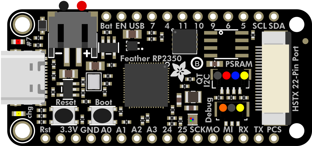
 Design with Adafruit Feather RP2350 in Cirkit Designer
Introduction
The Adafruit Feather RP2040 (Manufacturer Part ID: 6000) is a compact and versatile microcontroller board designed by Adafruit. It features the powerful RP2040 chip, which is a dual-core ARM Cortex-M0+ processor running at up to 133 MHz. This board is part of the Feather ecosystem, making it compatible with a wide range of FeatherWing add-ons for extended functionality. With built-in USB support, ample GPIO pins, and compatibility with various sensors and modules, the Feather RP2040 is ideal for prototyping, IoT applications, robotics, and more.
Explore Projects Built with Adafruit Feather RP2350
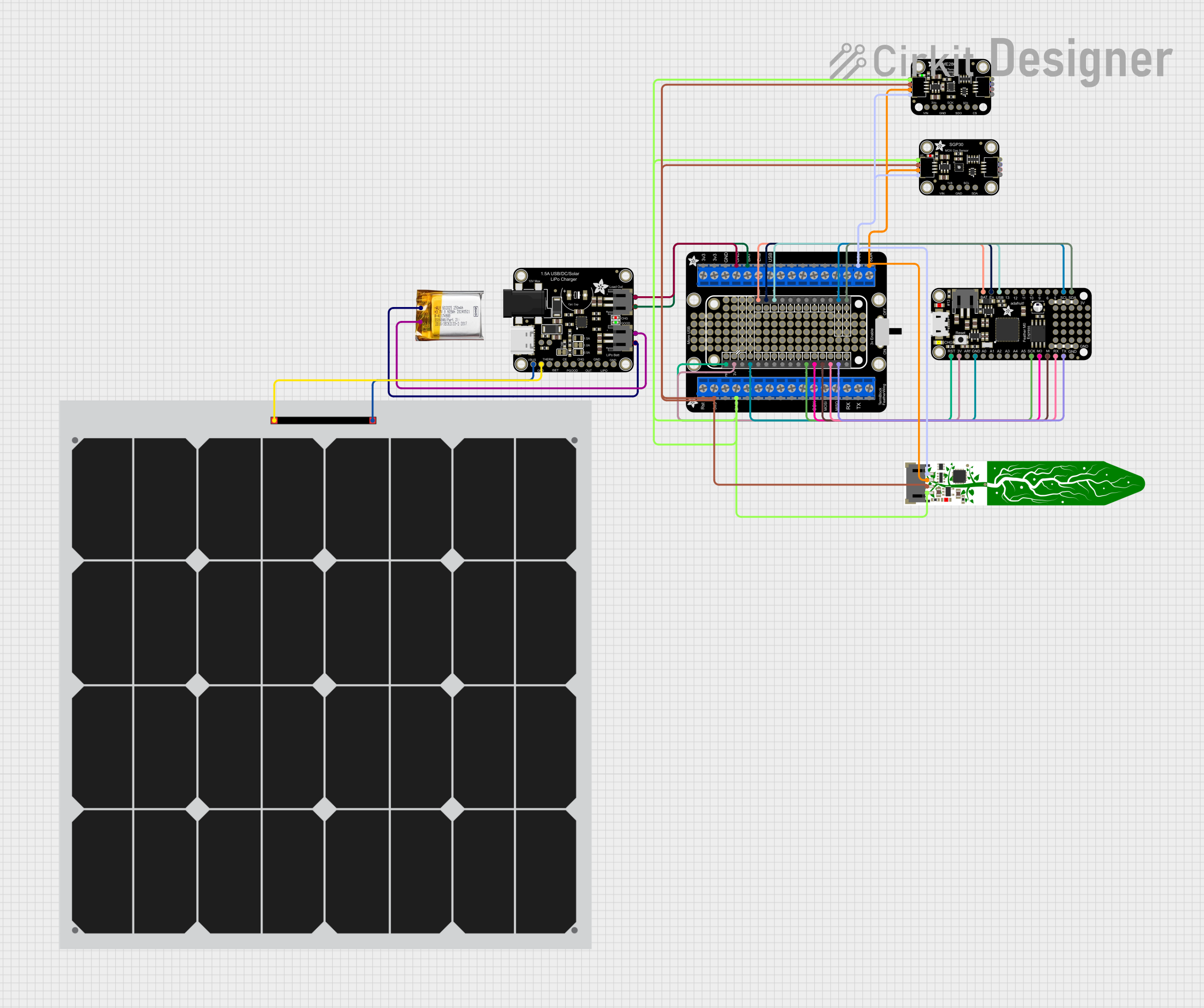 Open Project in Cirkit Designer
 Open Project in Cirkit Designer
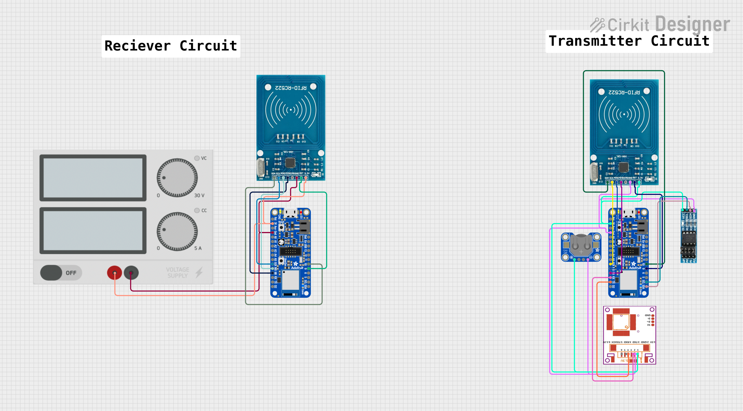 Open Project in Cirkit Designer
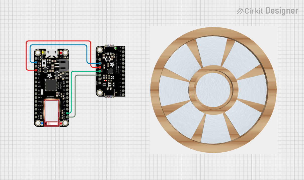 Open Project in Cirkit Designer
Explore Projects Built with Adafruit Feather RP2350
Open Project in Cirkit DesignerOpen Project in Cirkit DesignerOpen Project in Cirkit DesignerOpen Project in Cirkit DesignerCommon Applications
- IoT devices and smart home projects
- Robotics and motor control
- Data logging and sensor integration
- Wearable electronics
- Educational and hobbyist projects
Technical Specifications
The Adafruit Feather RP2040 is packed with features that make it a powerful and flexible microcontroller board. Below are its key technical details:
Key Features
- Microcontroller: RP2040 (Dual-core ARM Cortex-M0+ @ 133 MHz)
- Flash Memory: 8 MB (QSPI Flash)
- RAM: 264 KB SRAM
- USB: USB-C connector with native USB support
- GPIO Pins: 21 GPIO pins (3.3V logic)
- Analog Inputs: 4 ADC pins (12-bit resolution)
- Power Supply: 3.3V regulator (up to 500 mA output)
- Battery Support: JST connector for LiPo batteries (with charging circuit)
- Dimensions: 51.0 mm x 23.0 mm x 8.0 mm
- Weight: 5.0 grams
Pin Configuration
The Feather RP2040 has a total of 21 GPIO pins, which include digital I/O, analog inputs, and special-purpose pins. Below is the pinout description:
| Pin | Name | Description |
|---|---|---|
| 1 | GND | Ground connection |
| 2 | 3V3 | 3.3V power output |
| 3 | A0 (GP26) | Analog input 0 / GPIO26 |
| 4 | A1 (GP27) | Analog input 1 / GPIO27 |
| 5 | A2 (GP28) | Analog input 2 / GPIO28 |
| 6 | A3 (GP29) | Analog input 3 / GPIO29 |
| 7 | SDA (GP20) | I2C data line |
| 8 | SCL (GP21) | I2C clock line |
| 9 | TX (GP0) | UART transmit |
| 10 | RX (GP1) | UART receive |
| 11 | SCK (GP18) | SPI clock |
| 12 | MOSI (GP19) | SPI master-out slave-in |
| 13 | MISO (GP16) | SPI master-in slave-out |
| 14 | D5 (GP5) | Digital I/O |
| 15 | D6 (GP6) | Digital I/O |
| 16 | D9 (GP9) | Digital I/O |
| 17 | D10 (GP10) | Digital I/O |
| 18 | D11 (GP11) | Digital I/O |
| 19 | D12 (GP12) | Digital I/O |
| 20 | D13 (GP13) | Digital I/O (also connected to onboard LED) |
| 21 | BAT | Battery voltage input (for LiPo battery) |
Usage Instructions
The Adafruit Feather RP2040 is easy to use and can be programmed using popular development environments such as Arduino IDE, CircuitPython, or MicroPython. Below are the steps to get started and important considerations for using the board.
Getting Started
Powering the Board:
- Connect the Feather RP2040 to your computer using a USB-C cable.
- Alternatively, you can power it using a LiPo battery via the JST connector.
Installing Software:
- Download and install the Arduino IDE or CircuitPython firmware from the Adafruit website.
- For Arduino IDE, install the "Adafruit RP2040" board package via the Boards Manager.
Programming:
- Write your code in the Arduino IDE or CircuitPython editor.
- Upload the code to the board via the USB-C connection.
Example: Blinking the Onboard LED
Here is an example Arduino sketch to blink the onboard LED connected to pin D13:
// This example code blinks the onboard LED on the Adafruit Feather RP2040.
// The LED is connected to pin D13.

void setup() {
  pinMode(13, OUTPUT); // Set pin D13 as an output
}

void loop() {
  digitalWrite(13, HIGH); // Turn the LED on
  delay(500);             // Wait for 500 milliseconds
  digitalWrite(13, LOW);  // Turn the LED off
  delay(500);             // Wait for 500 milliseconds
}
Important Considerations
- Voltage Levels: The GPIO pins operate at 3.3V logic. Do not connect 5V signals directly to the pins.
- Battery Charging: If using a LiPo battery, ensure it is connected to the JST connector. The onboard charging circuit will handle charging when USB power is supplied.
- Pin Multiplexing: Some pins have multiple functions (e.g., GPIO, I2C, SPI). Refer to the pinout diagram to avoid conflicts.
Troubleshooting and FAQs
Common Issues
Board Not Recognized by Computer:
- Ensure the USB-C cable is a data cable (not charge-only).
- Check if the board is in bootloader mode by holding the BOOTSEL button while connecting it to your computer.
Code Upload Fails:
- Verify that the correct board and port are selected in the Arduino IDE.
- Ensure the Feather RP2040 is in bootloader mode if necessary.
No Output from GPIO Pins:
- Confirm that the pins are configured correctly in your code.
- Check for short circuits or incorrect wiring.
FAQs
Q: Can I use the Feather RP2040 with CircuitPython?
A: Yes, the Feather RP2040 is fully compatible with CircuitPython. You can download the CircuitPython firmware from Adafruit's website and upload it to the board.
Q: What is the maximum current output of the 3.3V pin?
A: The 3.3V regulator can supply up to 500 mA, but this includes the current used by the board itself.
Q: Can I connect multiple FeatherWings to the Feather RP2040?
A: Yes, the Feather RP2040 is part of the Feather ecosystem and supports stacking multiple FeatherWings for extended functionality.
Q: How do I reset the board?
A: Press the RESET button on the board to restart it. To enter bootloader mode, hold the BOOTSEL button while pressing RESET.
By following this documentation, you can effectively integrate the Adafruit Feather RP2040 into your projects and troubleshoot common issues with ease.