How to Use DC cable splitter: Examples, Pinouts, and Specs
Introduction
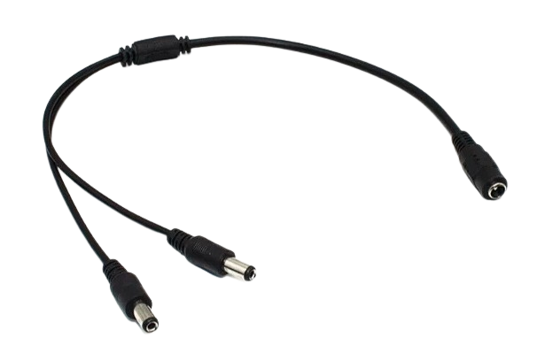
The DC Cable Splitter (Manufacturer: Arduino, Part ID: UNO) is a versatile device designed to divide a single DC power source into multiple outputs. This allows users to power multiple devices simultaneously from one power source, making it an essential tool for projects requiring multiple components or devices to operate in parallel.
Explore Projects Built with DC cable splitter


Explore Projects Built with DC cable splitter
Common Applications and Use Cases
- Powering multiple Arduino boards or sensors from a single DC power adapter.
- Distributing power to LED strips, small motors, or other low-power devices.
- Simplifying wiring in prototyping and DIY electronics projects.
- Reducing the need for multiple power adapters in compact setups.
Technical Specifications
The DC Cable Splitter is designed to handle low-voltage DC power distribution efficiently. Below are the key technical details:
| Specification | Details |
|---|---|
| Input Voltage Range | 5V to 24V DC |
| Maximum Current Rating | 5A (total across all outputs) |
| Number of Outputs | 2 to 4 (depending on model) |
| Connector Type | Standard DC barrel jack (5.5mm/2.1mm) |
| Cable Length | 30cm to 50cm (varies by model) |
| Operating Temperature | -20°C to 60°C |
| Insulation Material | PVC or equivalent |
Pin Configuration and Descriptions
The DC Cable Splitter does not have traditional pins but uses barrel connectors. Below is a description of the input and output connectors:
| Connector | Description |
|---|---|
| Input | Single DC barrel jack for power input |
| Outputs | Multiple DC barrel jacks for power distribution |
Usage Instructions
How to Use the DC Cable Splitter in a Circuit
- Connect the Input: Plug the DC power adapter into the input barrel jack of the splitter. Ensure the adapter's voltage and current ratings match the requirements of your devices.
- Connect the Outputs: Plug the devices you want to power into the output barrel jacks of the splitter. Ensure the total current draw of all connected devices does not exceed the splitter's maximum current rating (5A).
- Power On: Turn on the DC power adapter. All connected devices should now receive power.
Important Considerations and Best Practices
- Voltage Compatibility: Ensure all connected devices operate within the voltage range of the DC power adapter.
- Current Distribution: The total current draw of all connected devices must not exceed the adapter's or splitter's maximum current rating.
- Polarity: Verify the polarity of the DC barrel connectors (center positive) to avoid damage to your devices.
- Cable Length: Longer cables may introduce voltage drops. Use shorter cables for high-current applications.
- Heat Management: Avoid overloading the splitter to prevent overheating.
Example: Using the DC Cable Splitter with an Arduino UNO
The DC Cable Splitter can be used to power multiple Arduino UNO boards from a single DC power adapter. Below is an example setup:
- Use a 12V DC power adapter with a current rating of at least 2A.
- Connect the adapter to the input of the DC Cable Splitter.
- Plug the output connectors into the DC barrel jacks of the Arduino UNO boards.
- Power on the adapter, and all connected boards will receive power.
If you want to control the Arduino boards via USB while using the splitter for power, ensure the USB and DC power sources are properly isolated to avoid conflicts.
Troubleshooting and FAQs
Common Issues and Solutions
| Issue | Solution |
|---|---|
| Devices not powering on | Check the input power adapter's voltage and current ratings. Ensure proper connections. |
| Overheating of the splitter or adapter | Ensure the total current draw does not exceed the splitter's or adapter's rating. |
| Voltage drop across devices | Use shorter cables or a higher-quality power adapter to minimize voltage loss. |
| Devices behaving erratically | Verify that all devices are compatible with the input voltage and current. |
FAQs
Q: Can I use the DC Cable Splitter with devices requiring different voltages?
A: No, the splitter distributes the same input voltage to all outputs. Ensure all connected devices operate at the same voltage.
Q: Can I daisy-chain multiple splitters?
A: While possible, daisy-chaining is not recommended as it may lead to excessive voltage drops and overloading of the power source.
Q: Is the splitter compatible with USB-powered devices?
A: The splitter is designed for DC barrel jack connectors. To use it with USB-powered devices, you will need appropriate adapters.
By following these guidelines and best practices, the Arduino DC Cable Splitter (UNO) can be a reliable and efficient tool for powering multiple devices in your electronics projects.