How to Use PCB: Examples, Pinouts, and Specs
Introduction
The Arduino UNO PCB (Printed Circuit Board) is a fundamental component in the world of electronics and embedded systems. It mechanically supports and electrically connects electronic components using conductive tracks, pads, and other features etched from copper sheets laminated onto a non-conductive substrate. The Arduino UNO PCB is widely used in various applications, including prototyping, educational projects, and hobbyist electronics.
Explore Projects Built with PCB


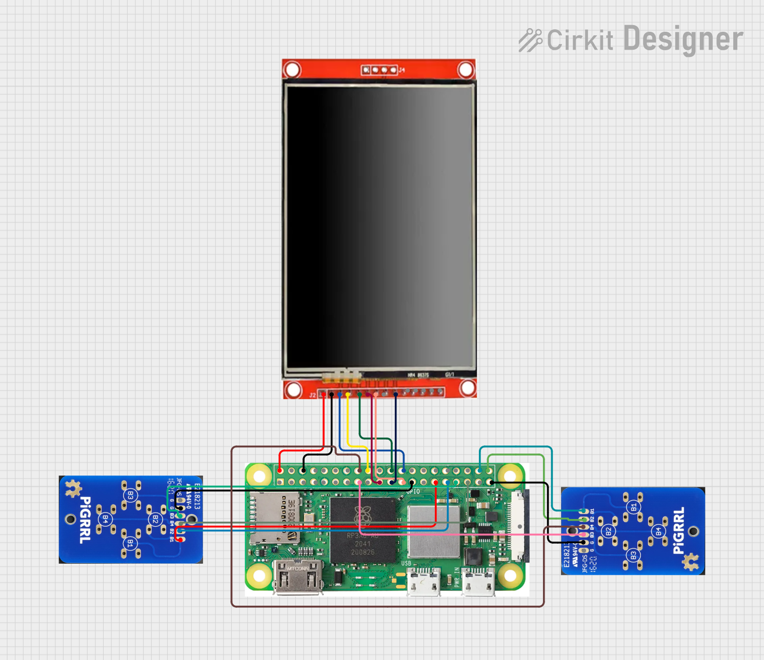

Explore Projects Built with PCB
Common Applications and Use Cases
- Prototyping: Ideal for testing and developing new electronic circuits.
- Educational Projects: Widely used in schools and universities for teaching electronics and programming.
- Hobbyist Projects: Popular among DIY enthusiasts for creating custom electronic devices.
- Embedded Systems: Used in various embedded applications for controlling devices and systems.
Technical Specifications
Key Technical Details
| Specification | Value |
|---|---|
| Manufacturer | ARDUINO |
| Part ID | UNO |
| Operating Voltage | 5V |
| Input Voltage | 7-12V |
| Digital I/O Pins | 14 (6 PWM output) |
| Analog Input Pins | 6 |
| DC Current per I/O Pin | 20 mA |
| Flash Memory | 32 KB (ATmega328P) |
| SRAM | 2 KB (ATmega328P) |
| EEPROM | 1 KB (ATmega328P) |
| Clock Speed | 16 MHz |
Pin Configuration and Descriptions
| Pin Number | Pin Name | Description |
|---|---|---|
| 1 | TX | Transmit data (UART) |
| 2 | RX | Receive data (UART) |
| 3 | GND | Ground |
| 4 | 5V | 5V power supply |
| 5 | 3.3V | 3.3V power supply |
| 6 | A0 | Analog input 0 |
| 7 | A1 | Analog input 1 |
| 8 | A2 | Analog input 2 |
| 9 | A3 | Analog input 3 |
| 10 | A4 | Analog input 4 |
| 11 | A5 | Analog input 5 |
| 12 | D0 | Digital I/O 0 |
| 13 | D1 | Digital I/O 1 |
| 14 | D2 | Digital I/O 2 |
| 15 | D3 | Digital I/O 3 (PWM) |
| 16 | D4 | Digital I/O 4 |
| 17 | D5 | Digital I/O 5 (PWM) |
| 18 | D6 | Digital I/O 6 (PWM) |
| 19 | D7 | Digital I/O 7 |
| 20 | D8 | Digital I/O 8 |
| 21 | D9 | Digital I/O 9 (PWM) |
| 22 | D10 | Digital I/O 10 (PWM) |
| 23 | D11 | Digital I/O 11 (PWM) |
| 24 | D12 | Digital I/O 12 |
| 25 | D13 | Digital I/O 13 (LED) |
| 26 | VIN | Input voltage to the Arduino board |
| 27 | GND | Ground |
| 28 | RESET | Reset the microcontroller |
Usage Instructions
How to Use the Component in a Circuit
Powering the Board:
- Connect the VIN pin to a power source (7-12V) or use the USB port for power.
- Ensure the GND pin is connected to the ground of the power source.
Connecting Components:
- Use the digital I/O pins (D0-D13) for digital signals.
- Use the analog input pins (A0-A5) for analog signals.
- Connect sensors, actuators, and other components to the appropriate pins.
Programming the Board:
- Connect the Arduino UNO to your computer using a USB cable.
- Open the Arduino IDE and select the correct board and port.
- Write your code and upload it to the board.
Important Considerations and Best Practices
- Avoid Overloading Pins: Ensure that the current drawn from any I/O pin does not exceed 20 mA.
- Proper Grounding: Always connect the GND pin to the ground of your circuit to avoid floating voltages.
- Use Decoupling Capacitors: Place decoupling capacitors close to the power pins of the board to filter out noise.
- Handle with Care: Avoid touching the PCB with bare hands to prevent static discharge damage.
Troubleshooting and FAQs
Common Issues Users Might Face
Board Not Recognized by Computer:
- Ensure the USB cable is properly connected.
- Check if the correct board and port are selected in the Arduino IDE.
- Try using a different USB cable or port.
Upload Error:
- Ensure no other program is using the COM port.
- Press the RESET button on the board before uploading.
- Check for any loose connections or damaged components.
Components Not Working:
- Verify the connections and ensure they match the pin configuration.
- Check if the components are functioning correctly.
- Ensure the code is correctly written and uploaded.
Solutions and Tips for Troubleshooting
- Reset the Board: Press the RESET button to restart the microcontroller.
- Check Power Supply: Ensure the board is receiving the correct voltage.
- Inspect Connections: Verify all connections are secure and correct.
- Use Serial Monitor: Utilize the Serial Monitor in the Arduino IDE to debug and monitor the board's output.
Example Code for Arduino UNO
// Blink LED on pin 13
void setup() {
  pinMode(13, OUTPUT); // Set pin 13 as an output
}

void loop() {
  digitalWrite(13, HIGH); // Turn the LED on
  delay(1000);            // Wait for 1 second
  digitalWrite(13, LOW);  // Turn the LED off
  delay(1000);            // Wait for 1 second
}
This simple code will blink the onboard LED connected to pin 13 of the Arduino UNO. It serves as a basic example to get started with the board.
By following this documentation, users can effectively utilize the Arduino UNO PCB in their projects, ensuring proper usage and troubleshooting common issues.