Cirkit Designer Logo
Cirkit Designer
Your all-in-one circuit design IDE
Home / 
Component Documentation

How to Use MAX6675: Examples, Pinouts, and Specs

Image of MAX6675
Cirkit Designer LogoDesign with MAX6675 in Cirkit Designer

Introduction

The MAX6675 is a digital temperature sensor designed to interface with K-type thermocouples, providing accurate temperature readings in a range of 0°C to 1024°C. It converts the thermocouple's analog signal into a 12-bit digital value and communicates with microcontrollers via the SPI (Serial Peripheral Interface) protocol. The MAX6675 is widely used in applications requiring precise temperature monitoring, such as industrial automation, HVAC systems, and laboratory equipment.

Explore Projects Built with MAX6675

Use Cirkit Designer to design, explore, and prototype these projects online. Some projects support real-time simulation. Click "Open Project" to start designing instantly!
Arduino Mega 2560 Based Multi-Channel Thermocouple Reader
Image of thermostat-test: A project utilizing MAX6675 in a practical application
This circuit is designed to interface with multiple MAX6675 thermocouple-to-digital converter modules using an Arduino Mega 2560 as the central processing unit. The Arduino reads temperature data from the MAX6675 modules over a shared SPI bus, with individual chip select (CS) lines for each module to enable multiplexing. The circuit is likely used for monitoring multiple temperature points, possibly in an industrial setting where precise temperature control and monitoring are critical.
Cirkit Designer LogoOpen Project in Cirkit Designer
ESP8266 NodeMCU Controlled Multi-Channel Thermocouple Interface
Image of Temperature Data Acquisition_Task2: A project utilizing MAX6675 in a practical application
This circuit is designed to interface multiple MAX6675 thermocouple-to-digital converter modules with an ESP8266 NodeMCU microcontroller. Each MAX6675 module is connected to a temperature sensor and the ESP8266 is configured to communicate with the modules via SPI to read temperature data. The ESP8266 NodeMCU manages the chip select (CS) lines individually for each MAX6675 module, allowing for multiple temperature readings from different sensors.
Cirkit Designer LogoOpen Project in Cirkit Designer
Arduino Mega 2560 Based Multi-Channel Thermocouple Temperature Monitoring System
Image of Proyecto H sala: A project utilizing MAX6675 in a practical application
This circuit is designed to read temperatures from multiple thermocouples using a series of MAX6675 modules interfaced with an Arduino Mega 2560 microcontroller. The Arduino collects temperature data from each thermocouple via the SPI interface, with individual chip select (CS) lines for each MAX6675 module, and outputs the readings to the serial monitor. Pull-up resistors are connected to the MISO lines to ensure proper logic levels are maintained for reliable SPI communication.
Cirkit Designer LogoOpen Project in Cirkit Designer
Arduino Mega 2560 and MAX6675 Thermocouple Temperature Sensor
Image of wiring arduino mega+max6675: A project utilizing MAX6675 in a practical application
This circuit consists of an Arduino Mega 2560 microcontroller connected to a MAX6675 thermocouple temperature sensor module. The Arduino provides power to the MAX6675 module and reads temperature data via digital pins, enabling temperature monitoring and data acquisition.
Cirkit Designer LogoOpen Project in Cirkit Designer

Explore Projects Built with MAX6675

Use Cirkit Designer to design, explore, and prototype these projects online. Some projects support real-time simulation. Click "Open Project" to start designing instantly!
Image of thermostat-test: A project utilizing MAX6675 in a practical application
Arduino Mega 2560 Based Multi-Channel Thermocouple Reader
This circuit is designed to interface with multiple MAX6675 thermocouple-to-digital converter modules using an Arduino Mega 2560 as the central processing unit. The Arduino reads temperature data from the MAX6675 modules over a shared SPI bus, with individual chip select (CS) lines for each module to enable multiplexing. The circuit is likely used for monitoring multiple temperature points, possibly in an industrial setting where precise temperature control and monitoring are critical.
Cirkit Designer LogoOpen Project in Cirkit Designer
Image of Temperature Data Acquisition_Task2: A project utilizing MAX6675 in a practical application
ESP8266 NodeMCU Controlled Multi-Channel Thermocouple Interface
This circuit is designed to interface multiple MAX6675 thermocouple-to-digital converter modules with an ESP8266 NodeMCU microcontroller. Each MAX6675 module is connected to a temperature sensor and the ESP8266 is configured to communicate with the modules via SPI to read temperature data. The ESP8266 NodeMCU manages the chip select (CS) lines individually for each MAX6675 module, allowing for multiple temperature readings from different sensors.
Cirkit Designer LogoOpen Project in Cirkit Designer
Image of Proyecto H sala: A project utilizing MAX6675 in a practical application
Arduino Mega 2560 Based Multi-Channel Thermocouple Temperature Monitoring System
This circuit is designed to read temperatures from multiple thermocouples using a series of MAX6675 modules interfaced with an Arduino Mega 2560 microcontroller. The Arduino collects temperature data from each thermocouple via the SPI interface, with individual chip select (CS) lines for each MAX6675 module, and outputs the readings to the serial monitor. Pull-up resistors are connected to the MISO lines to ensure proper logic levels are maintained for reliable SPI communication.
Cirkit Designer LogoOpen Project in Cirkit Designer
Image of wiring arduino mega+max6675: A project utilizing MAX6675 in a practical application
Arduino Mega 2560 and MAX6675 Thermocouple Temperature Sensor
This circuit consists of an Arduino Mega 2560 microcontroller connected to a MAX6675 thermocouple temperature sensor module. The Arduino provides power to the MAX6675 module and reads temperature data via digital pins, enabling temperature monitoring and data acquisition.
Cirkit Designer LogoOpen Project in Cirkit Designer

Technical Specifications

  • Temperature Range: 0°C to 1024°C
  • Resolution: 0.25°C
  • Accuracy: ±2°C (typical)
  • Supply Voltage: 3.0V to 5.5V
  • Current Consumption: 1.5mA (typical)
  • Communication Protocol: SPI (3-wire interface)
  • Thermocouple Compatibility: K-type
  • Output Format: 12-bit digital data
  • Cold-Junction Compensation: Built-in

Pin Configuration and Descriptions

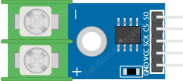
The MAX6675 is typically available in an 8-pin SOIC package. Below is the pinout and description:

Pin Number Pin Name Description
1 SO Serial Data Output (SPI data line)
2 CS Chip Select (active low, enables communication)
3 SCK Serial Clock Input (SPI clock line)
4 GND Ground (0V reference)
5 NC No Connection
6 NC No Connection
7 VCC Power Supply (3.0V to 5.5V)
8 T- Negative terminal for the thermocouple

Usage Instructions

How to Use the MAX6675 in a Circuit

  1. Power Supply: Connect the VCC pin to a 3.3V or 5V power source and the GND pin to the ground.
  2. Thermocouple Connection: Attach the K-type thermocouple to the T+ and T- pins. Ensure proper polarity (T+ is positive, T- is negative).
  3. SPI Communication:
    • Connect the SO pin to the microcontroller's MISO (Master In Slave Out) pin.
    • Connect the CS pin to a GPIO pin on the microcontroller for chip select.
    • Connect the SCK pin to the microcontroller's SPI clock pin.
  4. Pull-Up Resistor: Use a pull-up resistor on the CS line if required by your microcontroller.
  5. Cold-Junction Compensation: The MAX6675 automatically compensates for cold-junction temperature, so no additional circuitry is needed.

Arduino UNO Example Code

Below is an example of how to interface the MAX6675 with an Arduino UNO:

#include <SPI.h>

// Define MAX6675 connections
const int CS_PIN = 10;  // Chip Select pin
const int SCK_PIN = 13; // Serial Clock pin
const int SO_PIN = 12;  // Serial Data Output pin

void setup() {
  Serial.begin(9600); // Initialize serial communication
  pinMode(CS_PIN, OUTPUT); // Set CS pin as output
  digitalWrite(CS_PIN, HIGH); // Set CS pin high (inactive)
  SPI.begin(); // Initialize SPI communication
}

float readTemperature() {
  uint16_t value = 0;

  // Start communication with MAX6675
  digitalWrite(CS_PIN, LOW); // Activate chip select
  delay(1);

  // Read 16 bits of data from MAX6675
  value = SPI.transfer(0x00) << 8; // Read high byte
  value |= SPI.transfer(0x00);    // Read low byte

  digitalWrite(CS_PIN, HIGH); // Deactivate chip select

  // Check for thermocouple connection error
  if (value & 0x0004) {
    return NAN; // Return NaN if no thermocouple is connected
  }

  // Extract temperature data (bits 3-15) and convert to Celsius
  value >>= 3; // Shift out unused bits
  return value * 0.25; // Multiply by resolution (0.25°C per bit)
}

void loop() {
  float temperature = readTemperature(); // Read temperature
  if (isnan(temperature)) {
    Serial.println("Thermocouple not connected!");
  } else {
    Serial.print("Temperature: ");
    Serial.print(temperature);
    Serial.println(" °C");
  }
  delay(1000); // Wait 1 second before next reading
}

Important Considerations and Best Practices

  • Ensure the thermocouple is properly connected to the T+ and T- pins. Reversed polarity will result in incorrect readings.
  • Avoid long thermocouple wires or noisy environments, as they can introduce errors.
  • Use decoupling capacitors (e.g., 0.1µF) near the VCC pin to stabilize the power supply.
  • The MAX6675 is designed for K-type thermocouples only. Using other types will result in inaccurate readings.

Troubleshooting and FAQs

Common Issues and Solutions

  1. No Temperature Reading (NaN Output):

    • Ensure the thermocouple is securely connected to the T+ and T- pins.
    • Check for broken or damaged thermocouple wires.
    • Verify that the CS, SCK, and SO pins are correctly connected to the microcontroller.
  2. Incorrect Temperature Readings:

    • Confirm that the thermocouple is a K-type.
    • Check for electrical noise or interference in the circuit.
    • Ensure the power supply voltage is within the specified range (3.0V to 5.5V).
  3. SPI Communication Issues:

    • Verify the SPI clock speed. The MAX6675 supports clock speeds up to 4.3MHz.
    • Ensure the CS pin is toggled correctly (active low) during communication.

FAQs

Q: Can I use the MAX6675 with a 3.3V microcontroller?
A: Yes, the MAX6675 operates with a supply voltage of 3.0V to 5.5V, making it compatible with both 3.3V and 5V systems.

Q: What happens if the thermocouple is disconnected?
A: The MAX6675 sets the fault bit (D2) in the output data, and the temperature reading will be invalid (NaN in the example code).

Q: Can I use a different type of thermocouple with the MAX6675?
A: No, the MAX6675 is specifically designed for K-type thermocouples. Using other types will result in inaccurate readings.