How to Use ESP32-S3 DevKit-C: Examples, Pinouts, and Specs
Introduction
The ESP32-S3 DevKit-C is a development board manufactured by YK, featuring the powerful ESP32-S3 chip. This board is designed for IoT applications and prototyping, offering integrated Wi-Fi and Bluetooth connectivity. It supports a wide range of peripherals and interfaces, making it ideal for developers working on smart devices, home automation, wearables, and other connected applications.
Explore Projects Built with ESP32-S3 DevKit-C


Explore Projects Built with ESP32-S3 DevKit-C
Common Applications:
- IoT devices and smart home systems
- Wearable electronics
- Wireless sensor networks
- Industrial automation
- Prototyping for AI and machine learning applications
Technical Specifications
The ESP32-S3 DevKit-C is built around the ESP32-S3 chip, which is optimized for high performance and low power consumption. Below are the key technical details:
Key Features:
- Processor: Dual-core Xtensa LX7 CPU, up to 240 MHz
- Wireless Connectivity:
- Wi-Fi: 802.11 b/g/n (2.4 GHz)
- Bluetooth: Bluetooth 5.0 LE
- Memory:
- 512 KB SRAM
- 8 MB PSRAM (external)
- Flash Storage: 16 MB
- GPIO Pins: 45 (multiplexed with various peripherals)
- Interfaces:
- SPI, I2C, I2S, UART
- ADC (up to 12-bit resolution)
- DAC (2 channels)
- PWM
- USB OTG
- Operating Voltage: 3.3V
- Power Supply: USB-C or external 5V input
- Dimensions: 54 mm x 25 mm
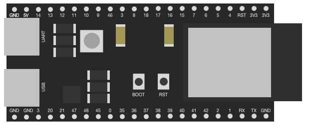
Pin Configuration and Descriptions
The ESP32-S3 DevKit-C features a 2-row pin header layout. Below is the pinout description:
| Pin Name | Function | Description |
|---|---|---|
| 3V3 | Power | 3.3V power output |
| GND | Ground | Ground connection |
| EN | Enable | Chip enable pin (active high) |
| IO0 | GPIO0 / Boot | General-purpose I/O, also used for boot mode selection |
| IO1-IO45 | GPIO | General-purpose I/O pins, multiplexed with peripherals |
| TXD0 | UART0 TX | UART0 transmit pin |
| RXD0 | UART0 RX | UART0 receive pin |
| SCL | I2C Clock | I2C clock line |
| SDA | I2C Data | I2C data line |
| ADC1_CH0-9 | ADC Channels | Analog-to-digital converter input channels |
| DAC1, DAC2 | Digital-to-Analog Converter | DAC output channels |
| USB_D+, USB_D- | USB Data Lines | USB OTG data lines |
Note: Some GPIO pins are reserved for specific functions or peripherals. Refer to the ESP32-S3 datasheet for detailed pin multiplexing information.
Usage Instructions
How to Use the ESP32-S3 DevKit-C in a Circuit
Powering the Board:
- Connect the board to your computer or a USB power source using a USB-C cable.
- Alternatively, supply 5V to the VIN pin for external power.
Programming the Board:
- Install the Arduino IDE or ESP-IDF (Espressif IoT Development Framework).
- Add the ESP32-S3 board support package to your development environment.
- Connect the board to your computer via USB and select the appropriate COM port.
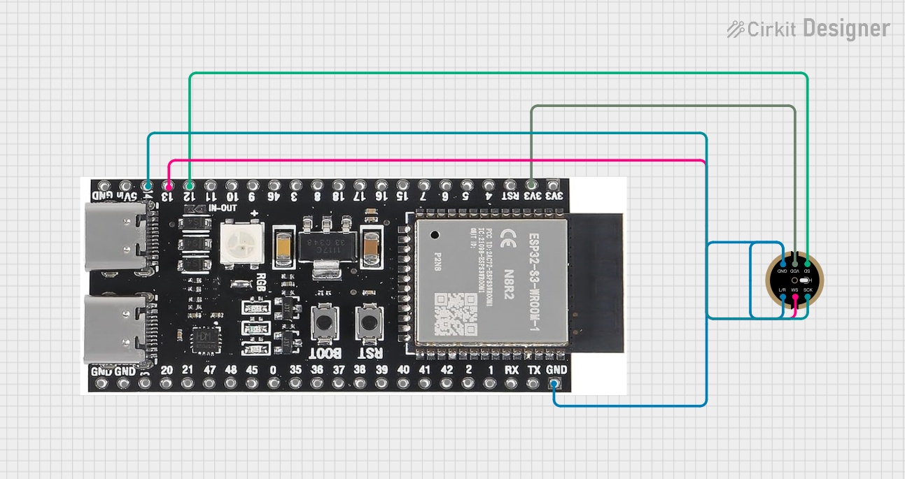
Connecting Peripherals:
- Use the GPIO pins to interface with sensors, actuators, or other devices.
- Ensure that the voltage levels of connected peripherals are compatible with the 3.3V logic of the ESP32-S3.
Uploading Code:
- Write your code in the Arduino IDE or ESP-IDF.
- Compile and upload the code to the board. The onboard bootloader will handle the flashing process.
Example Code: Blinking an LED
Below is an example of how to blink an LED connected to GPIO2 using the Arduino IDE:
// Define the GPIO pin where the LED is connected
const int ledPin = 2;

void setup() {
  // Set the LED pin as an output
  pinMode(ledPin, OUTPUT);
}

void loop() {
  // Turn the LED on
  digitalWrite(ledPin, HIGH);
  delay(1000); // Wait for 1 second

  // Turn the LED off
  digitalWrite(ledPin, LOW);
  delay(1000); // Wait for 1 second
}
Important Considerations:
- Voltage Levels: Ensure all connected peripherals operate at 3.3V logic levels to avoid damaging the board.
- Boot Mode: To enter bootloader mode manually, hold the IO0 button while pressing the EN button.
- Power Supply: Use a stable power source to avoid unexpected resets or malfunctions.
Troubleshooting and FAQs
Common Issues and Solutions:
Board Not Detected by Computer:
- Ensure the USB-C cable supports data transfer (not just charging).
- Check if the correct drivers for the ESP32-S3 are installed on your computer.
Code Upload Fails:
- Verify that the correct COM port is selected in the Arduino IDE or ESP-IDF.
- Ensure the board is in bootloader mode by holding IO0 and pressing EN during upload.
Wi-Fi Connection Issues:
- Double-check the SSID and password in your code.
- Ensure the Wi-Fi network operates on the 2.4 GHz band (ESP32-S3 does not support 5 GHz).
GPIO Pin Not Working:
- Confirm that the pin is not reserved for other functions (e.g., USB, ADC).
- Check for short circuits or incorrect wiring.
FAQs:
Q: Can I power the board with a battery?
- A: Yes, you can use a 3.7V LiPo battery connected to the appropriate pins, but ensure proper voltage regulation.
Q: Does the ESP32-S3 support over-the-air (OTA) updates?
- A: Yes, the ESP32-S3 supports OTA updates, which can be implemented using the Arduino IDE or ESP-IDF.
Q: Can I use the ESP32-S3 with MicroPython?
- A: Yes, the ESP32-S3 is compatible with MicroPython. Flash the MicroPython firmware to the board to get started.
By following this documentation, you can effectively utilize the ESP32-S3 DevKit-C for your IoT and prototyping projects.