How to Use Proffieboard v2.2: Examples, Pinouts, and Specs
Introduction
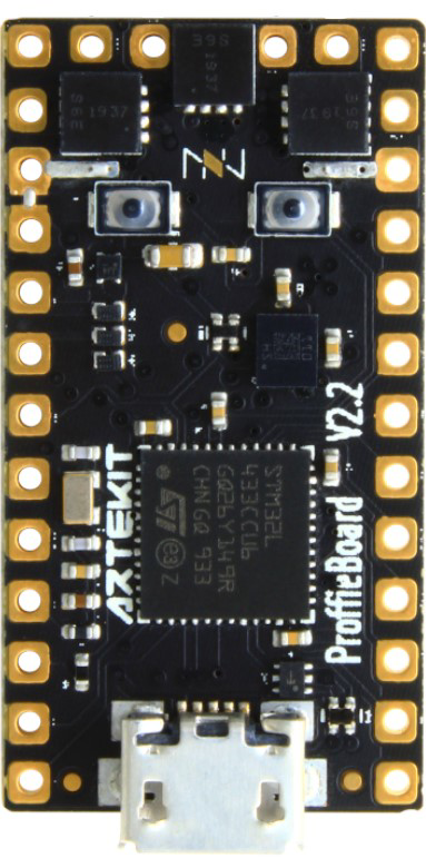
The Proffieboard v2.2, manufactured by Proffie, is a highly versatile sound and control board designed specifically for custom lightsabers. It offers advanced sound effects, customizable settings, and support for various LED configurations, making it a popular choice among lightsaber enthusiasts and prop builders. With its powerful microcontroller and extensive customization options, the Proffieboard v2.2 enables users to create highly realistic and immersive lightsaber experiences.
Explore Projects Built with Proffieboard v2.2
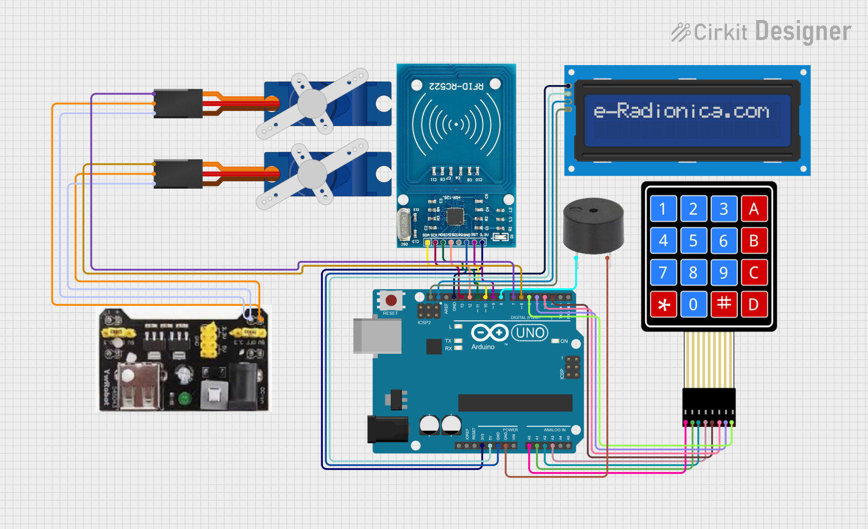

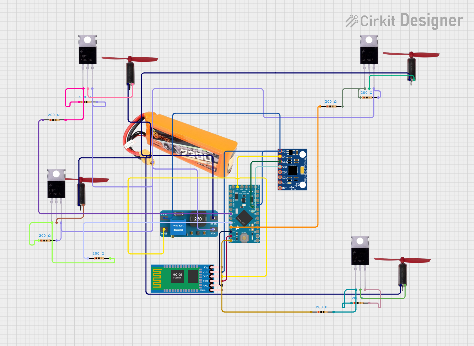

Explore Projects Built with Proffieboard v2.2
Common Applications and Use Cases
- Custom lightsaber builds for cosplay, collections, or dueling
- Prop building for movies, theater, or fan projects
- Interactive LED-based projects requiring sound and motion control
- Advanced hobbyist projects involving sound and light synchronization
Technical Specifications
The Proffieboard v2.2 is a compact yet powerful board with the following key specifications:
| Specification | Details |
|---|---|
| Microcontroller | STM32F405RGT6 (32-bit ARM Cortex-M4, 168 MHz) |
| Flash Memory | 16 MB (for sound fonts, effects, and configurations) |
| RAM | 192 KB |
| Power Input | 3.7V - 5.5V (supports single-cell Li-Ion/Li-Po batteries) |
| LED Support | Neopixel (WS2812/WS2813) and in-hilt LEDs |
| Motion Sensors | MPU6050 (6-axis accelerometer and gyroscope) |
| Audio Output | High-quality mono audio output (supports 4Ω or 8Ω speakers) |
| USB Interface | Micro-USB (for programming and configuration) |
| Dimensions | 1.3" x 0.5" (33 mm x 13 mm) |
Pin Configuration and Descriptions
The Proffieboard v2.2 features multiple pins for connecting LEDs, speakers, buttons, and other components. Below is the pin configuration:
| Pin Name | Type | Description |
|---|---|---|
| VBAT | Power Input | Connect to the positive terminal of the battery (3.7V - 5.5V). |
| GND | Ground | Common ground for all components. |
| LED1 | Data Output | Data line for Neopixel LEDs (main blade). |
| LED2 | Data Output | Data line for Neopixel LEDs (secondary blade or accents). |
| SPK+ | Audio Output | Positive terminal for the speaker. |
| SPK- | Audio Output | Negative terminal for the speaker. |
| BUTTON | Digital Input | Connect to the main activation button. |
| AUX | Digital Input | Connect to the auxiliary button (for additional effects). |
| USB+ | USB Data | USB data line for programming and configuration. |
| USB- | USB Data | USB data line for programming and configuration. |
| SDA | I2C Data | Data line for I2C communication (e.g., with additional sensors). |
| SCL | I2C Clock | Clock line for I2C communication. |
| BAT+ | Power Output | Battery voltage output for powering external components. |
| 3.3V | Power Output | 3.3V regulated output for powering low-power external components. |
Usage Instructions
How to Use the Proffieboard v2.2 in a Circuit
- Power Supply: Connect a single-cell Li-Ion or Li-Po battery (3.7V nominal) to the VBAT and GND pins. Ensure proper polarity to avoid damage.
- LED Connection:
- For Neopixel LEDs, connect the data line of the LED strip to the LED1 or LED2 pin.
- Use a 330-ohm resistor in series with the data line to protect the board.
- Connect the LED strip's power and ground to the battery and GND, respectively.
- Speaker: Connect a 4Ω or 8Ω speaker to the SPK+ and SPK- pins.
- Buttons:
- Connect the main activation button to the BUTTON pin and GND.
- Connect the auxiliary button to the AUX pin and GND.
- Programming: Use a micro-USB cable to connect the Proffieboard to your computer. Install the required drivers and software (e.g., Arduino IDE with Proffieboard support) to upload configurations and sound fonts.
Important Considerations and Best Practices
- Battery Protection: Use a battery with built-in protection circuitry to prevent overcharging or over-discharging.
- Heat Management: Avoid prolonged operation at maximum brightness to prevent overheating.
- Wiring: Use appropriate wire gauges for power and data connections to ensure reliability.
- Firmware Updates: Regularly check for firmware updates to access new features and bug fixes.
Example Code for Arduino IDE
Below is an example of a basic configuration for the Proffieboard v2.2:
// Include the Proffieboard library
#include "ProffieOS.h"

// Define the blade configuration
BladeConfig blades[] = {
  { WS281XBladePtr<144, bladePin1, Color8::Red>(), // Main blade with 144 LEDs
    WS281XBladePtr<32, bladePin2, Color8::Blue>()  // Accent blade with 32 LEDs
  }
};

// Define the sound font
SoundFontConfig soundFonts[] = {
  { "font1", 0, 255, 0 } // Load "font1" with default volume
};

// Main setup function
void setup() {
  ProffieOS::begin(blades, soundFonts); // Initialize ProffieOS
}

// Main loop function
void loop() {
  ProffieOS::loop(); // Run ProffieOS
}
Note: Replace
bladePin1andbladePin2with the actual pin numbers used for your LED connections. Ensure the ProffieOS library is installed in your Arduino IDE.
Troubleshooting and FAQs
Common Issues and Solutions
Board Not Recognized by Computer:
- Ensure the USB cable is a data cable (not charge-only).
- Check that the Proffieboard drivers are installed correctly.
- Try a different USB port or cable.
LEDs Not Lighting Up:
- Verify the data line connection and resistor placement.
- Check the LED configuration in the firmware.
- Ensure the battery is fully charged.
No Sound from Speaker:
- Confirm the speaker connections to SPK+ and SPK-.
- Check the sound font configuration in the firmware.
- Test with a different speaker to rule out hardware issues.
Board Overheating:
- Reduce the brightness of the LEDs in the configuration.
- Ensure proper ventilation and avoid prolonged high-power operation.
FAQs
Q: Can I use the Proffieboard v2.2 with in-hilt LEDs instead of Neopixels?
A: Yes, the Proffieboard supports in-hilt LEDs. You will need to configure the firmware accordingly.
Q: How do I update the firmware on the Proffieboard?
A: Connect the board to your computer via USB, open the Arduino IDE, and upload the updated firmware. Ensure the correct board and port are selected in the IDE.
Q: What is the maximum number of LEDs supported?
A: The Proffieboard can support up to 300 Neopixel LEDs, but performance may vary based on power supply and configuration.
Q: Can I use additional sensors with the Proffieboard?
A: Yes, the I2C pins (SDA and SCL) allow you to connect additional sensors, such as temperature or proximity sensors.
By following this documentation, you can effectively integrate the Proffieboard v2.2 into your custom lightsaber or other LED-based projects.