How to Use MAGNETIC CONTACTOR: Examples, Pinouts, and Specs
Introduction
A magnetic contactor is an electrically controlled switch designed for switching power circuits. Manufactured by CIRKIT (Part ID: MAGNETIC CONTACTOR), this component is ideal for controlling high-current applications. Unlike standard relays, magnetic contactors are specifically engineered to handle large electrical loads, making them indispensable in industrial and commercial environments.
Explore Projects Built with MAGNETIC CONTACTOR


Explore Projects Built with MAGNETIC CONTACTOR
Common Applications and Use Cases
- Motor control in industrial machinery
- HVAC systems for switching compressors and fans
- Lighting control in large facilities
- Power distribution systems
- Automation systems requiring high-current switching
Technical Specifications
Key Technical Details
- Manufacturer: CIRKIT
- Part ID: MAGNETIC CONTACTOR
- Rated Voltage: 24V DC (coil voltage)
- Rated Current: 32A (main contacts)
- Contact Configuration: 3-pole (3NO)
- Operating Frequency: 50/60 Hz
- Insulation Voltage: 690V
- Mechanical Life: 10 million operations
- Electrical Life: 1 million operations (at rated load)
- Operating Temperature: -25°C to +55°C
- Mounting: DIN rail or panel mount
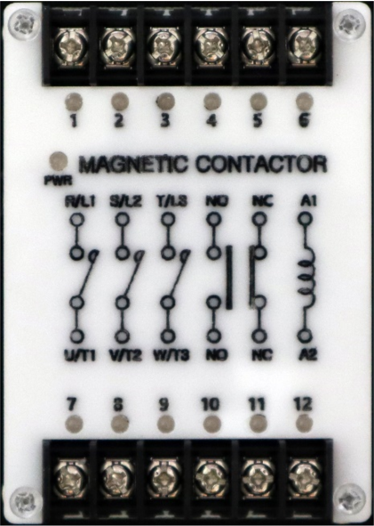
Pin Configuration and Descriptions
The magnetic contactor has two main sections: the coil terminals and the main contact terminals. Below is the pin configuration:
Coil Terminals
| Pin Label | Description | Notes |
|---|---|---|
| A1 | Coil positive terminal | Connect to the positive voltage source. |
| A2 | Coil negative terminal | Connect to the ground or negative terminal. |
Main Contact Terminals
| Pin Label | Description | Notes |
|---|---|---|
| L1 | Input for phase 1 | Connect to the power source. |
| L2 | Input for phase 2 | Connect to the power source. |
| L3 | Input for phase 3 | Connect to the power source. |
| T1 | Output for phase 1 | Connect to the load. |
| T2 | Output for phase 2 | Connect to the load. |
| T3 | Output for phase 3 | Connect to the load. |
Auxiliary Contacts (if applicable)
| Pin Label | Description | Notes |
|---|---|---|
| NO | Normally Open auxiliary contact | Used for control circuits. |
| NC | Normally Closed auxiliary contact | Used for control circuits. |
Usage Instructions
How to Use the Component in a Circuit
Power the Coil:
- Connect the coil terminals (A1 and A2) to a 24V DC power source. Ensure the polarity is correct.
- When the coil is energized, the electromagnet activates, closing the main contacts (L1-T1, L2-T2, L3-T3).
Connect the Load:
- Connect the power source to the input terminals (L1, L2, L3).
- Connect the load (e.g., motor, lighting system) to the output terminals (T1, T2, T3).
Control Circuit (Optional):
- Use the auxiliary contacts (NO/NC) for control or feedback purposes in automation systems.
Mounting:
- Secure the contactor to a DIN rail or panel using the provided mounting slots.
Important Considerations and Best Practices
- Voltage Matching: Ensure the coil voltage matches the rated 24V DC. Overvoltage or undervoltage can damage the coil.
- Current Rating: Verify that the load current does not exceed the rated 32A.
- Overload Protection: Use an appropriate overload relay or circuit breaker to protect the contactor and connected equipment.
- Wiring: Use appropriately rated wires for the current and voltage levels. Ensure all connections are secure.
- Environment: Avoid exposure to excessive moisture, dust, or temperatures outside the -25°C to +55°C range.
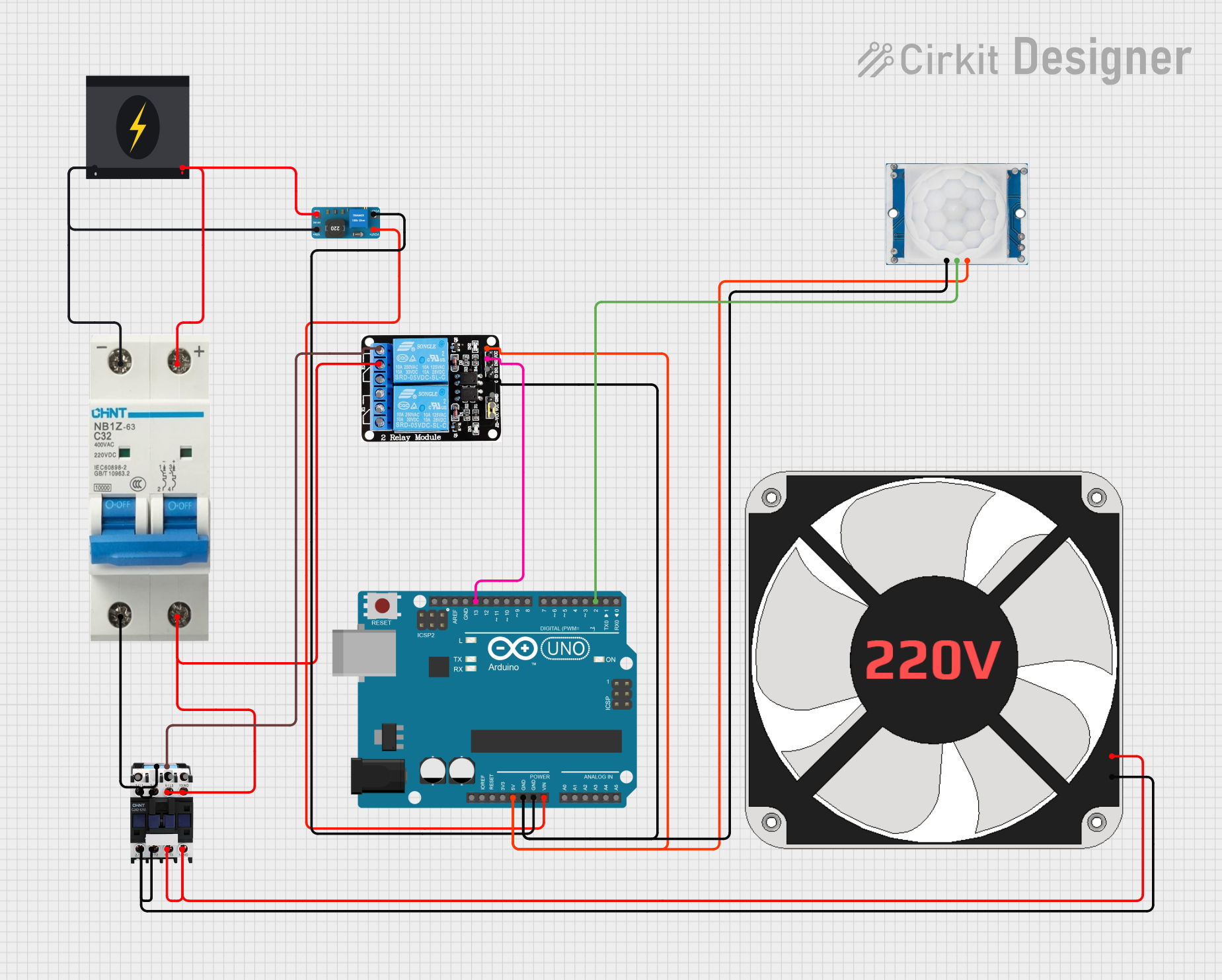
Example: Controlling a Motor with Arduino UNO
The magnetic contactor can be controlled using an Arduino UNO. Below is an example circuit and code to control a motor using the contactor.
Circuit Description
- The Arduino controls the contactor coil via a relay module.
- The contactor switches the motor on/off based on the Arduino's signal.
Code Example
// Magnetic Contactor Control with Arduino UNO
// This code toggles the contactor coil using a relay module connected to pin 7.

const int relayPin = 7; // Pin connected to the relay module

void setup() {
  pinMode(relayPin, OUTPUT); // Set relay pin as output
  digitalWrite(relayPin, LOW); // Ensure relay is off at startup
}

void loop() {
  // Turn on the contactor (energize the coil)
  digitalWrite(relayPin, HIGH);
  delay(5000); // Keep the contactor on for 5 seconds

  // Turn off the contactor (de-energize the coil)
  digitalWrite(relayPin, LOW);
  delay(5000); // Keep the contactor off for 5 seconds
}
Note: Ensure the relay module is rated for the contactor's coil voltage and current.
Troubleshooting and FAQs
Common Issues and Solutions
Contactor Does Not Activate:
- Cause: Coil voltage is incorrect or insufficient.
- Solution: Verify the power supply voltage and ensure it matches the rated 24V DC.
Excessive Heating:
- Cause: Overcurrent through the main contacts.
- Solution: Check the load current and ensure it does not exceed 32A. Use an overload relay if necessary.
Chattering Noise:
- Cause: Unstable power supply to the coil.
- Solution: Use a stable DC power source and check for loose connections.
Auxiliary Contacts Not Working:
- Cause: Miswiring or damaged auxiliary contacts.
- Solution: Verify the wiring and test the auxiliary contacts with a multimeter.
FAQs
Q: Can I use this contactor for single-phase loads?
A: Yes, connect only one phase (L1-T1) and leave the other terminals unconnected.Q: Is the contactor suitable for DC loads?
A: This contactor is primarily designed for AC loads. For DC loads, consult the manufacturer for compatibility.Q: How do I know if the contactor is faulty?
A: Test the coil resistance with a multimeter. A very high or infinite resistance indicates a damaged coil.Q: Can I mount the contactor horizontally?
A: Yes, the contactor can be mounted in any orientation, but ensure proper ventilation.
This concludes the documentation for the CIRKIT MAGNETIC CONTACTOR. For further assistance, refer to the manufacturer's datasheet or contact technical support.