How to Use outseal plc V3: Examples, Pinouts, and Specs
Introduction
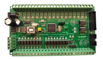
The Outseal PLC V3 is a programmable logic controller (PLC) designed for industrial automation applications. It is engineered to provide reliable and efficient control of machinery and processes in real-time. With its compact design, versatile input/output (I/O) options, and support for multiple communication protocols, the Outseal PLC V3 is ideal for a wide range of automation tasks, including manufacturing, process control, and building management systems.
Explore Projects Built with outseal plc V3


Explore Projects Built with outseal plc V3
Common Applications and Use Cases
- Industrial machinery control
- Conveyor belt automation
- Process monitoring and control
- Building automation systems (e.g., HVAC, lighting)
- Data acquisition and remote monitoring
- Integration with SCADA systems
Technical Specifications
Key Technical Details
| Parameter | Specification |
|---|---|
| Supply Voltage | 24V DC ±10% |
| Power Consumption | 5W (typical) |
| Digital Inputs | 16 channels (24V DC, sink/source) |
| Digital Outputs | 16 channels (relay or transistor) |
| Analog Inputs | 4 channels (0-10V or 4-20mA) |
| Analog Outputs | 2 channels (0-10V or 4-20mA) |
| Communication Protocols | Modbus RTU, Modbus TCP, CAN, RS-485 |
| Programming Language | Ladder Logic, Function Block Diagram |
| Operating Temperature | -20°C to 60°C |
| Dimensions | 120mm x 90mm x 60mm |
| Mounting | DIN rail |
Pin Configuration and Descriptions
Digital Inputs
| Pin Number | Description | Signal Type |
|---|---|---|
| DI1-DI16 | Digital Input Channels 1-16 | 24V DC |
| COM | Common Ground for Inputs | GND |
Digital Outputs
| Pin Number | Description | Signal Type |
|---|---|---|
| DO1-DO16 | Digital Output Channels 1-16 | Relay/Transistor |
| COM | Common Ground for Outputs | GND |
Analog Inputs
| Pin Number | Description | Signal Type |
|---|---|---|
| AI1-AI4 | Analog Input Channels 1-4 | 0-10V / 4-20mA |
| AGND | Analog Ground | GND |
Analog Outputs
| Pin Number | Description | Signal Type |
|---|---|---|
| AO1-AO2 | Analog Output Channels 1-2 | 0-10V / 4-20mA |
| AGND | Analog Ground | GND |
Communication Ports
| Port | Description | Protocol |
|---|---|---|
| RS-485 | Serial Communication Port | Modbus RTU |
| Ethernet | Network Communication Port | Modbus TCP |
| CAN | Controller Area Network Port | CAN Protocol |
Usage Instructions
How to Use the Outseal PLC V3 in a Circuit
- Power Supply: Connect a 24V DC power supply to the PLC's power input terminals. Ensure the polarity is correct.
- Digital Inputs: Wire the input devices (e.g., sensors, switches) to the DI1-DI16 pins. Use the COM pin as the common ground.
- Digital Outputs: Connect output devices (e.g., relays, actuators) to the DO1-DO16 pins. Use the COM pin as the common ground.
- Analog Inputs: Connect analog sensors (e.g., temperature, pressure) to the AI1-AI4 pins. Configure the input type (voltage or current) in the PLC software.
- Analog Outputs: Wire analog actuators (e.g., valves, motors) to the AO1-AO2 pins. Configure the output type (voltage or current) in the PLC software.
- Communication: Use the RS-485, Ethernet, or CAN ports to connect the PLC to other devices or systems. Configure the communication protocol in the PLC software.
Important Considerations and Best Practices
- Power Supply: Use a regulated 24V DC power supply to avoid voltage fluctuations.
- Grounding: Ensure proper grounding to minimize electrical noise and interference.
- Input/Output Protection: Use external protection devices (e.g., diodes, fuses) to safeguard the PLC from overvoltage or short circuits.
- Programming: Use the Outseal PLC V3 programming software to create and upload control logic. Follow the manufacturer's guidelines for programming.
- Communication: Match the communication settings (e.g., baud rate, parity) between the PLC and connected devices.
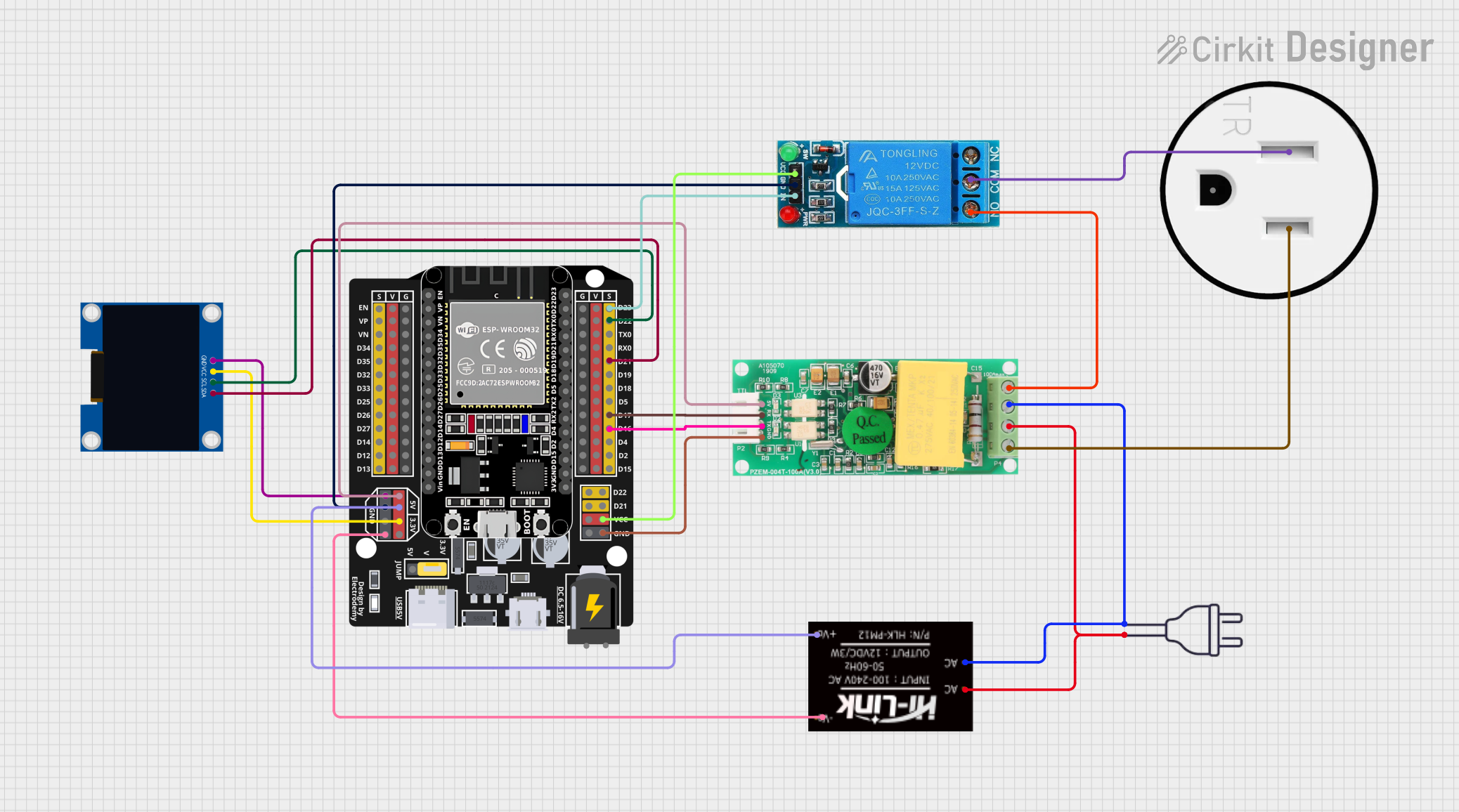
Example Code for Arduino UNO Integration
The Outseal PLC V3 can communicate with an Arduino UNO via Modbus RTU over RS-485. Below is an example code snippet:
#include <ModbusMaster.h>

// Instantiate ModbusMaster object
ModbusMaster node;

void setup() {
  // Initialize serial communication for RS-485
  Serial.begin(9600);

  // Initialize Modbus communication
  node.begin(1, Serial); // Set Modbus ID to 1
}

void loop() {
  uint8_t result;
  uint16_t data;

  // Read a digital input (e.g., DI1) from the PLC
  result = node.readDiscreteInputs(0x0000, 1); // Address 0x0000, 1 input
  if (result == node.ku8MBSuccess) {
    data = node.getResponseBuffer(0);
    Serial.print("DI1 State: ");
    Serial.println(data);
  }

  // Write a digital output (e.g., DO1) to the PLC
  result = node.writeSingleCoil(0x0000, 1); // Address 0x0000, set DO1 to HIGH
  if (result == node.ku8MBSuccess) {
    Serial.println("DO1 set to HIGH");
  }

  delay(1000); // Wait 1 second
}
Note: Use an RS-485 module to interface the Arduino UNO with the Outseal PLC V3. Ensure proper wiring and termination resistors for reliable communication.
Troubleshooting and FAQs
Common Issues and Solutions
PLC Not Powering On
- Cause: Incorrect power supply voltage or polarity.
- Solution: Verify the power supply voltage is 24V DC and check the polarity.
Inputs/Outputs Not Responding
- Cause: Incorrect wiring or configuration.
- Solution: Double-check the wiring and ensure the I/O channels are correctly configured in the PLC software.
Communication Failure
- Cause: Mismatched communication settings or faulty cables.
- Solution: Verify the baud rate, parity, and other communication settings. Check the cables for damage.
Analog Signals Not Accurate
- Cause: Incorrect input/output type or electrical noise.
- Solution: Ensure the correct type (voltage or current) is selected in the PLC software. Use shielded cables to reduce noise.
FAQs
Q: Can the Outseal PLC V3 be programmed using open-source software?
A: No, the Outseal PLC V3 requires the proprietary programming software provided by the manufacturer.Q: What is the maximum cable length for RS-485 communication?
A: The maximum recommended cable length for RS-485 is 1200 meters, depending on the baud rate and cable quality.Q: Can the PLC operate in extreme environments?
A: The PLC is designed to operate within a temperature range of -20°C to 60°C. For harsher environments, additional protection may be required.Q: How do I update the firmware?
A: Firmware updates can be performed using the manufacturer's software and a USB or Ethernet connection. Follow the instructions provided in the user manual.