Cirkit Designer Logo
Cirkit Designer
Your all-in-one circuit design IDE
Home / 
Component Documentation

How to Use Green Button: Examples, Pinouts, and Specs

Image of Green Button
Cirkit Designer LogoDesign with Green Button in Cirkit Designer

Introduction

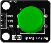
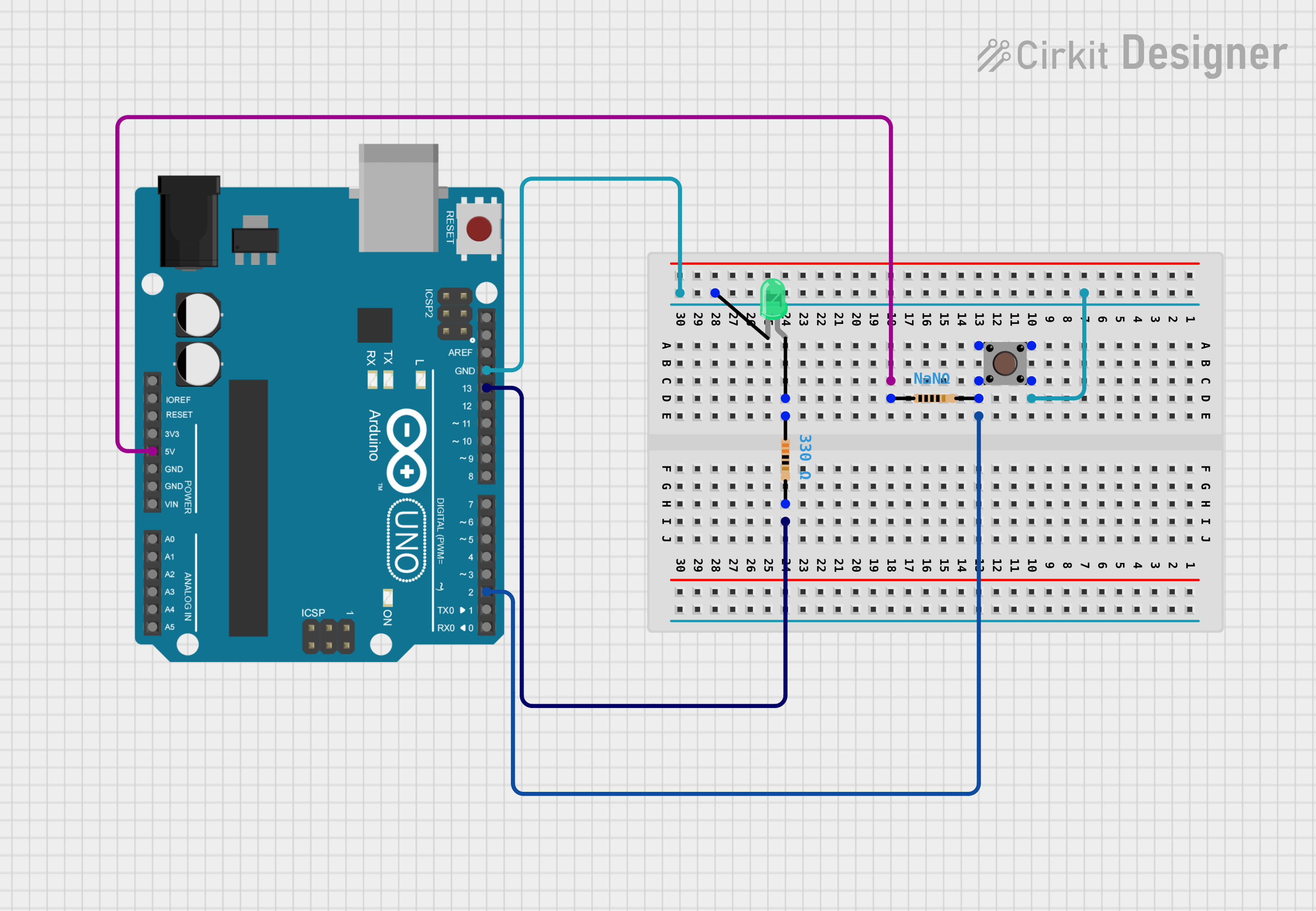
The Green Button is a user interface component that is widely used in electronic projects to trigger actions or confirm selections. It is a momentary push-button switch that is often illuminated with a green LED to indicate an active or 'go' state. This button is commonly found in applications such as control panels, user input devices, and interactive projects.

Explore Projects Built with Green Button

Use Cirkit Designer to design, explore, and prototype these projects online. Some projects support real-time simulation. Click "Open Project" to start designing instantly!
Arduino 101 LED Control with Push Button
Image of led on off ckt4: A project utilizing Green Button in a practical application
This circuit uses an Arduino 101 to control a green LED via a push button. When the button is pressed, the Arduino reads the input and turns on the LED; when the button is released, the LED turns off.
Cirkit Designer LogoOpen Project in Cirkit Designer
Arduino UNO Controlled LED with Pushbutton
Image of one green led & pull down: A project utilizing Green Button in a practical application
This circuit features an Arduino UNO configured to control a green LED using a pushbutton. The LED is connected to digital pin D13 through a 330 Ohm resistor, and the pushbutton is connected to digital pin D2 with a pull-down resistor to ground. When the button is pressed, the Arduino turns on the LED; when released, the LED turns off.
Cirkit Designer LogoOpen Project in Cirkit Designer
Arduino Mega 2560 Emergency Alert System with Panic Button and Vital Monitoring
Image of AHMS: A project utilizing Green Button in a practical application
This circuit is a health monitoring system using an Arduino Mega 2560, a green button, and a loudspeaker. The system monitors vital signs and triggers an emergency alert when the button is pressed, sending notifications and playing a voice alert.
Cirkit Designer LogoOpen Project in Cirkit Designer
Arduino UNO Controlled LED with Pushbutton
Image of one green led, one button, pull-up: A project utilizing Green Button in a practical application
This circuit features an Arduino UNO configured to control a green LED using a pushbutton. The button is debounced with a resistor and uses the Arduino's internal pull-up resistor, turning the LED on when pressed. The LED is connected to a digital pin through a current-limiting resistor to prevent damage to the LED.
Cirkit Designer LogoOpen Project in Cirkit Designer

Explore Projects Built with Green Button

Use Cirkit Designer to design, explore, and prototype these projects online. Some projects support real-time simulation. Click "Open Project" to start designing instantly!
Image of led on off ckt4: A project utilizing Green Button in a practical application
Arduino 101 LED Control with Push Button
This circuit uses an Arduino 101 to control a green LED via a push button. When the button is pressed, the Arduino reads the input and turns on the LED; when the button is released, the LED turns off.
Cirkit Designer LogoOpen Project in Cirkit Designer
Image of one green led & pull down: A project utilizing Green Button in a practical application
Arduino UNO Controlled LED with Pushbutton
This circuit features an Arduino UNO configured to control a green LED using a pushbutton. The LED is connected to digital pin D13 through a 330 Ohm resistor, and the pushbutton is connected to digital pin D2 with a pull-down resistor to ground. When the button is pressed, the Arduino turns on the LED; when released, the LED turns off.
Cirkit Designer LogoOpen Project in Cirkit Designer
Image of AHMS: A project utilizing Green Button in a practical application
Arduino Mega 2560 Emergency Alert System with Panic Button and Vital Monitoring
This circuit is a health monitoring system using an Arduino Mega 2560, a green button, and a loudspeaker. The system monitors vital signs and triggers an emergency alert when the button is pressed, sending notifications and playing a voice alert.
Cirkit Designer LogoOpen Project in Cirkit Designer
Image of one green led, one button, pull-up: A project utilizing Green Button in a practical application
Arduino UNO Controlled LED with Pushbutton
This circuit features an Arduino UNO configured to control a green LED using a pushbutton. The button is debounced with a resistor and uses the Arduino's internal pull-up resistor, turning the LED on when pressed. The LED is connected to a digital pin through a current-limiting resistor to prevent damage to the LED.
Cirkit Designer LogoOpen Project in Cirkit Designer

Common Applications and Use Cases

  • Starting or stopping a process
  • User input for interactive projects
  • Confirmation of selections in a menu
  • Initiating a sequence of events in a circuit

Technical Specifications

Key Technical Details

  • Voltage Rating: 3.3V to 5V
  • Current Rating: 20mA (LED), 10mA (Switch)
  • Power Rating: 100mW (LED), 0.5W (Switch)
  • Contact Type: Normally Open (NO)
  • Switch Bounce Time: <10ms
  • LED Color: Green
  • Operating Temperature: -10°C to 50°C

Pin Configuration and Descriptions

Pin Number Description Notes
1 LED Anode (+) Connect to positive voltage
2 LED Cathode (-) Connect to ground through a resistor
3 Switch Contact 1 Connect to input pin or ground
4 Switch Contact 2 Connect to ground or input pin

Usage Instructions

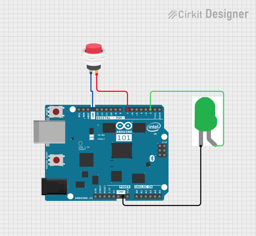
How to Use the Green Button in a Circuit

  1. LED Connection:

    • Connect the LED anode (Pin 1) to a digital output pin on your microcontroller.
    • Connect the LED cathode (Pin 2) to ground through a current-limiting resistor (typically 220Ω for 5V operation).
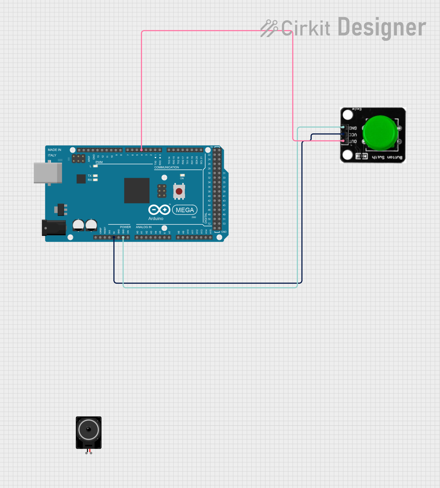
  2. Switch Connection:

    • Connect one switch contact (Pin 3) to an input pin on your microcontroller.
    • Connect the other switch contact (Pin 4) to ground.
    • Enable the internal pull-up resistor on the microcontroller's input pin to detect the button press.

Important Considerations and Best Practices

  • Always use a current-limiting resistor with the LED to prevent damage.
  • Debounce the button input either through hardware (e.g., a capacitor) or software to avoid false triggering.
  • Ensure the voltage rating of the button matches the voltage of your circuit to prevent damage.

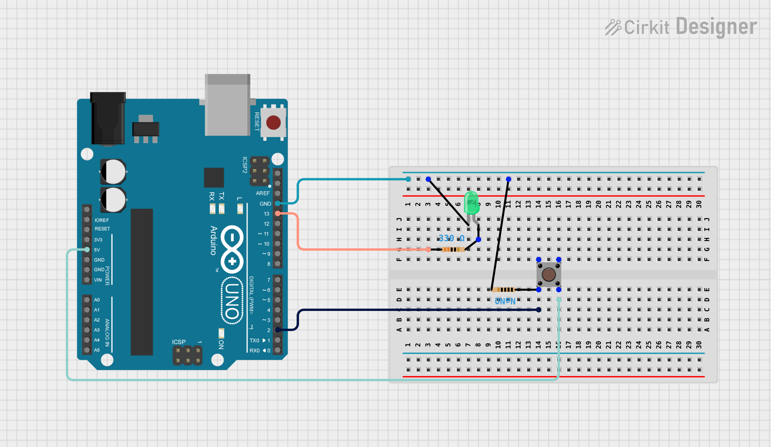
Example Code for Arduino UNO

// Define pin connections
const int buttonPin = 2; // Pin connected to button switch
const int ledPin = 13;   // Pin connected to LED anode

void setup() {
  pinMode(ledPin, OUTPUT);      // Set LED pin as output
  pinMode(buttonPin, INPUT_PULLUP); // Set button pin as input with internal pull-up

  digitalWrite(ledPin, LOW);    // Turn off LED initially
}

void loop() {
  // Check if button is pressed (logic LOW when pressed due to pull-up)
  if (digitalRead(buttonPin) == LOW) {
    digitalWrite(ledPin, HIGH); // Turn on LED
  } else {
    digitalWrite(ledPin, LOW);  // Turn off LED
  }
}

Troubleshooting and FAQs

Common Issues

  • LED not lighting up: Check the LED polarity and ensure the current-limiting resistor is correctly placed.
  • Button not responding: Verify the button is correctly wired and the input pin is configured with a pull-up resistor.
  • Unstable button state: Implement software debouncing or add a hardware debounce circuit.

Solutions and Tips for Troubleshooting

  • Double-check all connections against the pin configuration table.
  • Use a multimeter to ensure there is continuity in the button circuit when pressed.
  • Replace the current-limiting resistor if the LED is too dim or not lighting up.

FAQs

Q: Can I use the Green Button with a 3.3V system? A: Yes, the Green Button can operate at 3.3V, but ensure to adjust the current-limiting resistor for the LED accordingly.

Q: How do I debounce the button in software? A: Implement a delay after detecting a button press or use a library that handles debouncing.

Q: Is it necessary to use a pull-up resistor with the button? A: If your microcontroller has an internal pull-up resistor, you can use that instead of an external one. Otherwise, an external pull-up resistor is necessary.

Remember to keep your documentation up-to-date with any changes to the component or its usage. This ensures that users always have the latest information for their projects.