How to Use Power Meter : Examples, Pinouts, and Specs
Introduction
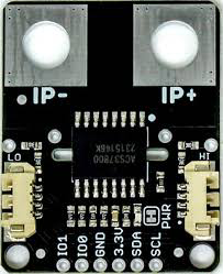
The SmartElex ACS37800 Power Meter is a highly accurate device designed to measure electrical power in a circuit. It provides real-time power consumption data, typically displayed in watts, making it an essential tool for monitoring and managing energy usage. This power meter integrates seamlessly into various applications, offering precise measurements for both AC and DC systems.
Explore Projects Built with Power Meter
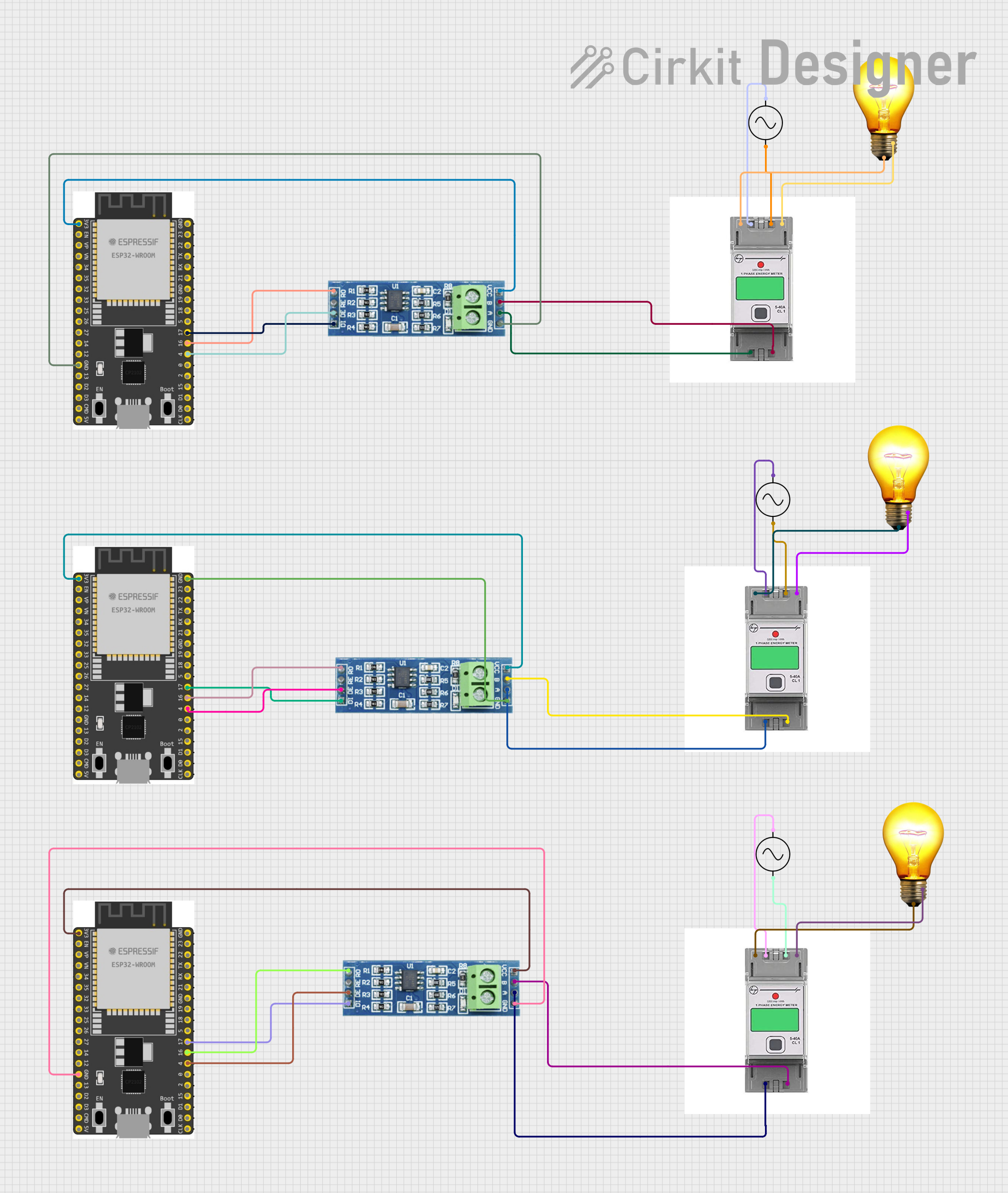
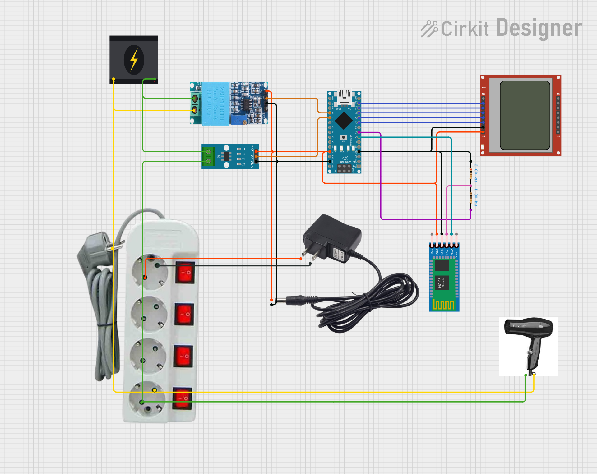

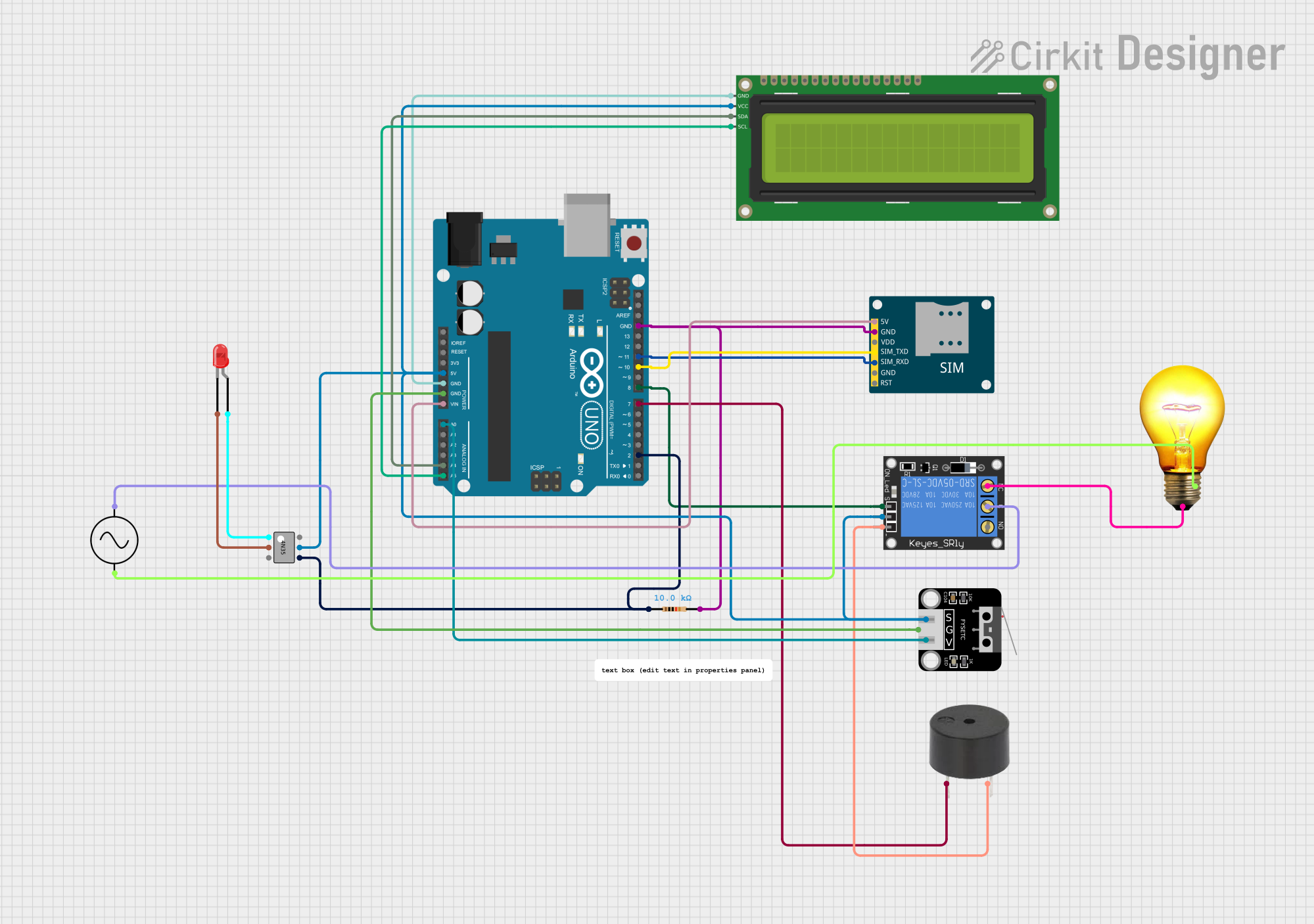
Explore Projects Built with Power Meter
Common Applications and Use Cases
- Home energy monitoring systems
- Industrial power management
- Renewable energy systems (e.g., solar and wind power)
- Electric vehicle charging stations
- IoT-based energy tracking solutions
Technical Specifications
The ACS37800 Power Meter is a robust and versatile component with the following key specifications:
| Parameter | Value |
|---|---|
| Supply Voltage (Vcc) | 3.3V to 5.5V |
| Measurement Voltage Range | Up to 240V AC or DC |
| Current Measurement Range | ±50A (depending on configuration) |
| Power Measurement Range | Up to 12kW |
| Accuracy | ±1% |
| Communication Interface | I2C |
| Operating Temperature | -40°C to +125°C |
| Package Type | SOIC-16 |
Pin Configuration and Descriptions
The ACS37800 features a 16-pin SOIC package. Below is the pinout and description:
| Pin Number | Pin Name | Description |
|---|---|---|
| 1 | VCC | Power supply input (3.3V to 5.5V) |
| 2 | GND | Ground |
| 3 | IP+ | Positive current input |
| 4 | IP- | Negative current input |
| 5 | VP+ | Positive voltage input |
| 6 | VP- | Negative voltage input |
| 7 | SDA | I2C data line |
| 8 | SCL | I2C clock line |
| 9-16 | NC | No connection |
Usage Instructions
How to Use the ACS37800 in a Circuit
- Power Supply: Connect the VCC pin to a 3.3V or 5V power source and the GND pin to the ground.
- Voltage Measurement: Connect the VP+ and VP- pins across the load or circuit where voltage needs to be measured.
- Current Measurement: Pass the current-carrying conductor through the IP+ and IP- pins for current sensing.
- I2C Communication: Connect the SDA and SCL pins to the corresponding I2C pins on your microcontroller (e.g., Arduino UNO).
- Pull-Up Resistors: Use pull-up resistors (typically 4.7kΩ) on the SDA and SCL lines for proper I2C communication.
Important Considerations and Best Practices
- Ensure the voltage and current inputs do not exceed the specified ranges to avoid damage.
- Use proper isolation techniques when measuring high voltages or currents.
- Calibrate the power meter for improved accuracy in your specific application.
- Keep the I2C lines as short as possible to minimize noise and ensure reliable communication.
Example Code for Arduino UNO
Below is an example Arduino sketch to interface the ACS37800 with an Arduino UNO using I2C:
#include <Wire.h>

// I2C address of the ACS37800 (default is 0x40)
#define ACS37800_ADDR 0x40

void setup() {
  Wire.begin(); // Initialize I2C communication
  Serial.begin(9600); // Initialize serial communication for debugging

  // Print a message to indicate setup is complete
  Serial.println("ACS37800 Power Meter Initialized");
}

void loop() {
  Wire.beginTransmission(ACS37800_ADDR); // Start communication with ACS37800
  Wire.write(0x00); // Request data from the power register (example register)
  Wire.endTransmission(false); // End transmission but keep the connection active

  Wire.requestFrom(ACS37800_ADDR, 2); // Request 2 bytes of data
  if (Wire.available() == 2) {
    uint16_t powerData = Wire.read() << 8 | Wire.read(); // Combine the two bytes
    float power = powerData * 0.1; // Convert raw data to watts (example scaling)
    Serial.print("Power: ");
    Serial.print(power);
    Serial.println(" W");
  } else {
    Serial.println("Error: No data received");
  }

  delay(1000); // Wait 1 second before the next reading
}
Notes:
- Replace
0x00in theWire.write()function with the actual register address for power data, as specified in the ACS37800 datasheet. - Adjust the scaling factor (
0.1in the example) based on your specific configuration.
Troubleshooting and FAQs
Common Issues and Solutions
No Data Received via I2C
- Ensure the SDA and SCL lines are properly connected.
- Verify that pull-up resistors are installed on the I2C lines.
- Check the I2C address of the ACS37800 and update the code if necessary.
Inaccurate Power Readings
- Verify that the voltage and current inputs are within the specified ranges.
- Perform calibration to account for any offsets or scaling errors.
- Ensure proper isolation and grounding to minimize noise.
Device Overheating
- Check for excessive current or voltage beyond the rated limits.
- Ensure adequate ventilation and heat dissipation in your circuit design.
FAQs
Q: Can the ACS37800 measure both AC and DC power?
A: Yes, the ACS37800 is capable of measuring both AC and DC power accurately.
Q: What is the maximum current the ACS37800 can measure?
A: The ACS37800 can measure currents up to ±50A, depending on the configuration.
Q: Is the ACS37800 compatible with 3.3V microcontrollers?
A: Yes, the ACS37800 operates with a supply voltage range of 3.3V to 5.5V, making it compatible with 3.3V microcontrollers.
Q: How do I calibrate the ACS37800?
A: Calibration involves applying known voltage and current values and adjusting the scaling factors in your code to match the measured values.
By following this documentation, you can effectively integrate the SmartElex ACS37800 Power Meter into your projects for accurate and reliable power measurement.