How to Use Voltage Regulator: Examples, Pinouts, and Specs
Introduction
A voltage regulator is an electronic component designed to maintain a constant output voltage level, regardless of variations in input voltage or load conditions. It ensures stable power delivery to sensitive electronic devices, protecting them from voltage fluctuations that could cause damage or erratic behavior.
Explore Projects Built with Voltage Regulator


Explore Projects Built with Voltage Regulator
Common Applications and Use Cases
- Power supply circuits for microcontrollers, sensors, and other electronic devices.
- Battery-powered systems to regulate voltage as the battery discharges.
- Voltage stabilization in audio equipment to reduce noise and distortion.
- Industrial and automotive systems requiring consistent voltage levels.
Technical Specifications
Below are the general technical specifications for a common linear voltage regulator, such as the LM7805 (5V output):
| Parameter | Value |
|---|---|
| Input Voltage Range | 7V to 35V |
| Output Voltage | 5V ± 2% |
| Maximum Output Current | 1.5A |
| Dropout Voltage | 2V (typical) |
| Operating Temperature | -40°C to +125°C |
| Quiescent Current | 5mA (typical) |
Pin Configuration and Descriptions
The LM7805 voltage regulator has three pins, as described below:
| Pin Number | Pin Name | Description |
|---|---|---|
| 1 | Input (IN) | Connects to the unregulated input voltage source. |
| 2 | Ground (GND) | Common ground for input and output. |
| 3 | Output (OUT) | Provides the regulated output voltage. |
Usage Instructions
How to Use the Voltage Regulator in a Circuit
- Connect the Input Voltage: Attach the unregulated DC voltage source to the
Input (IN)pin. Ensure the input voltage is within the specified range (e.g., 7V to 35V for the LM7805). - Connect the Ground: Link the
Ground (GND)pin to the common ground of the circuit. - Connect the Output Voltage: Use the
Output (OUT)pin to power your load or circuit requiring a regulated voltage. - Add Capacitors: Place capacitors at the input and output for stability:
- A 0.33µF capacitor between the
Input (IN)pin and ground. - A 0.1µF capacitor between the
Output (OUT)pin and ground.
- A 0.33µF capacitor between the
Important Considerations and Best Practices
- Heat Dissipation: Voltage regulators can generate heat, especially at high input voltages or currents. Use a heatsink if necessary to prevent overheating.
- Input Voltage: Ensure the input voltage is at least 2V higher than the desired output voltage (dropout voltage).
- Load Current: Do not exceed the maximum output current rating to avoid damaging the regulator.
- Bypass Capacitors: Always use the recommended capacitors to prevent oscillations and ensure stable operation.
Example: Using a Voltage Regulator with an Arduino UNO
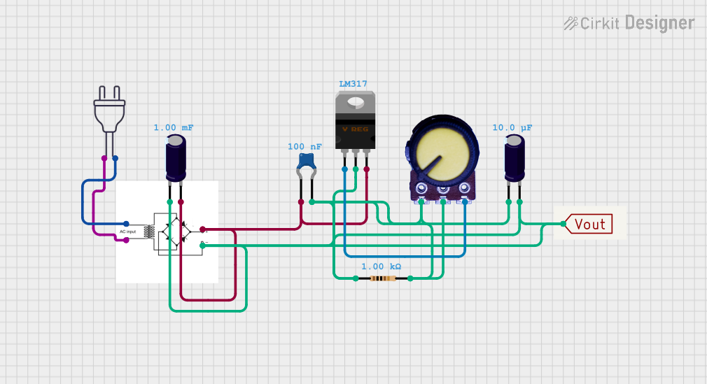
Below is an example of how to use the LM7805 to power an Arduino UNO with a 12V input source:
Circuit Diagram
- Connect the 12V input to the
Input (IN)pin of the LM7805. - Connect the
Output (OUT)pin to the Arduino's 5V pin. - Connect the
Ground (GND)pin to the Arduino's GND pin.
Arduino Code
// Example code to blink an LED connected to pin 13 of the Arduino UNO
// Ensure the Arduino is powered via the LM7805 voltage regulator.

void setup() {
  pinMode(13, OUTPUT); // Set pin 13 as an output
}

void loop() {
  digitalWrite(13, HIGH); // Turn the LED on
  delay(1000);            // Wait for 1 second
  digitalWrite(13, LOW);  // Turn the LED off
  delay(1000);            // Wait for 1 second
}
Troubleshooting and FAQs
Common Issues and Solutions
Regulator Overheating
- Cause: Excessive input voltage or current.
- Solution: Use a heatsink or reduce the input voltage.
Output Voltage Not Stable
- Cause: Missing or incorrect bypass capacitors.
- Solution: Add the recommended capacitors (0.33µF at input, 0.1µF at output).
No Output Voltage
- Cause: Incorrect wiring or damaged regulator.
- Solution: Verify connections and replace the regulator if necessary.
Oscillations or Noise
- Cause: Insufficient decoupling or long wires.
- Solution: Use shorter wires and ensure proper capacitor placement.
FAQs
Q: Can I use the LM7805 to power a 3.3V device?
- A: No, the LM7805 outputs 5V. Use a 3.3V regulator like the LM1117-3.3 instead.
Q: What happens if the input voltage drops below 7V?
- A: The regulator may fail to maintain a stable 5V output, leading to erratic behavior.
Q: Can I connect multiple voltage regulators in parallel for higher current?
- A: No, voltage regulators are not designed to share current evenly. Use a higher-current regulator instead.
By following this documentation, you can effectively use a voltage regulator to ensure stable and reliable power for your electronic projects.