How to Use pwm: Examples, Pinouts, and Specs
Introduction
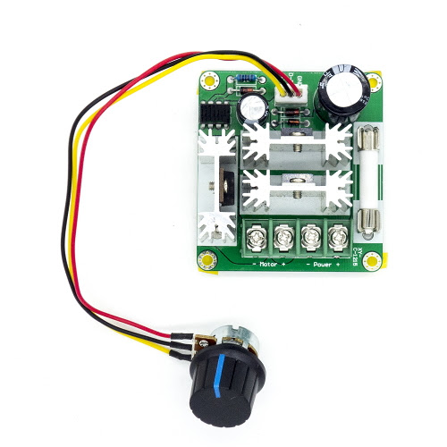
A Pulse Width Modulation (PWM) controller is an electronic component or module that modulates the width of pulses in a signal to control the amount of power delivered to a load. By varying the duty cycle (the ratio of the pulse's ON time to the total period), the PWM controller can effectively manage the power supplied to devices such as motors, LEDs, and heaters. PWM is widely used in applications requiring precise control of power, speed, or brightness.
Explore Projects Built with pwm


Explore Projects Built with pwm
Common Applications and Use Cases
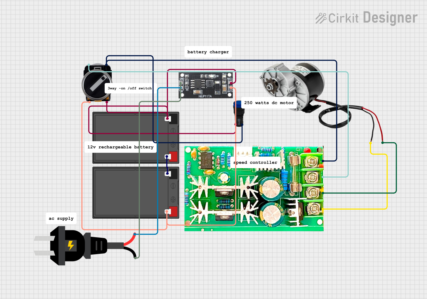
- Motor Speed Control: Adjusting the speed of DC motors in robotics, fans, and industrial equipment.
- LED Dimming: Controlling the brightness of LEDs in lighting systems.
- Power Regulation: Efficiently managing power delivery in power supplies and converters.
- Audio Signal Generation: Producing audio tones or signals in embedded systems.
- Temperature Control: Regulating heating elements in temperature-sensitive applications.
Technical Specifications
Below are the general technical specifications for a typical PWM controller. Note that specific values may vary depending on the exact model or manufacturer.
Key Technical Details
| Parameter | Value/Range |
|---|---|
| Input Voltage | 3.3V to 24V (varies by model) |
| Output Voltage | Matches input voltage (pass-through) |
| Output Current | Up to 10A (varies by model) |
| Frequency Range | 100 Hz to 100 kHz |
| Duty Cycle Range | 0% to 100% |
| Efficiency | >90% |
| Control Interface | Analog (potentiometer) or digital (MCU) |
Pin Configuration and Descriptions
| Pin Name | Description |
|---|---|
| VCC | Power supply input (3.3V to 24V, depending on the model). |
| GND | Ground connection. |
| PWM_OUT | PWM signal output to the load (e.g., motor, LED). |
| CTRL | Control input for adjusting the duty cycle (analog voltage or digital PWM). |
Usage Instructions
How to Use the PWM Controller in a Circuit
- Power the Controller: Connect the VCC pin to a suitable power source (e.g., 12V for motor control) and the GND pin to the ground of the circuit.
- Connect the Load: Attach the load (e.g., motor or LED) to the PWM_OUT pin and ensure the load's power requirements match the controller's output specifications.
- Control the Duty Cycle:
- For analog control: Use a potentiometer or an analog voltage signal on the CTRL pin.
- For digital control: Use a microcontroller (e.g., Arduino) to generate a PWM signal on the CTRL pin.
- Adjust the Frequency (if applicable): Some PWM controllers allow frequency adjustment via onboard settings or external components.
Important Considerations and Best Practices
- Match Voltage and Current Ratings: Ensure the input voltage and load current do not exceed the controller's specifications.
- Use Proper Heat Dissipation: For high-power applications, ensure adequate cooling (e.g., heatsinks) to prevent overheating.
- Filter Noise: Add capacitors or inductors to reduce noise in sensitive circuits.
- Avoid Overloading: Do not connect loads that exceed the controller's maximum current rating.
Example: Using PWM with an Arduino UNO
Below is an example of controlling an LED's brightness using PWM on an Arduino UNO.
// Example: LED dimming using PWM on Arduino UNO
// Connect the LED's positive terminal to pin 9 (via a resistor) and the negative terminal to GND.

int ledPin = 9; // PWM pin connected to the LED

void setup() {
  pinMode(ledPin, OUTPUT); // Set pin 9 as an output
}

void loop() {
  for (int brightness = 0; brightness <= 255; brightness++) {
    analogWrite(ledPin, brightness); // Increase brightness
    delay(10); // Wait 10ms for smooth transition
  }
  for (int brightness = 255; brightness >= 0; brightness--) {
    analogWrite(ledPin, brightness); // Decrease brightness
    delay(10); // Wait 10ms for smooth transition
  }
}
Troubleshooting and FAQs
Common Issues and Solutions
PWM Output Not Working:
- Cause: Incorrect power supply or loose connections.
- Solution: Verify the input voltage and ensure all connections are secure.
Load Not Responding to Duty Cycle Changes:
- Cause: Load requirements exceed the controller's output capacity.
- Solution: Check the load's voltage and current ratings and ensure they are within the controller's limits.
Excessive Heat Generation:
- Cause: High current draw or insufficient cooling.
- Solution: Add a heatsink or fan to dissipate heat effectively.
Noise in the Circuit:
- Cause: High-frequency switching causing interference.
- Solution: Use decoupling capacitors or inductors to filter noise.
FAQs
Q: Can I use a PWM controller with an AC load?
A: No, PWM controllers are typically designed for DC loads. Use an AC dimmer circuit for AC loads.Q: How do I calculate the power delivered to the load?
A: Power = Voltage × Current × Duty Cycle. For example, at 12V, 2A, and 50% duty cycle, the power is 12 × 2 × 0.5 = 12W.Q: Can I control multiple loads with one PWM controller?
A: Yes, but ensure the total current draw of all loads does not exceed the controller's maximum current rating.Q: What happens if I set the duty cycle to 0% or 100%?
A: At 0%, the load receives no power. At 100%, the load receives full power, effectively bypassing PWM control.