Cirkit Designer Logo
Cirkit Designer
Your all-in-one circuit design IDE
Home / 
Component Documentation

How to Use keypad-p: Examples, Pinouts, and Specs

Image of keypad-p
Cirkit Designer LogoDesign with keypad-p in Cirkit Designer

Introduction

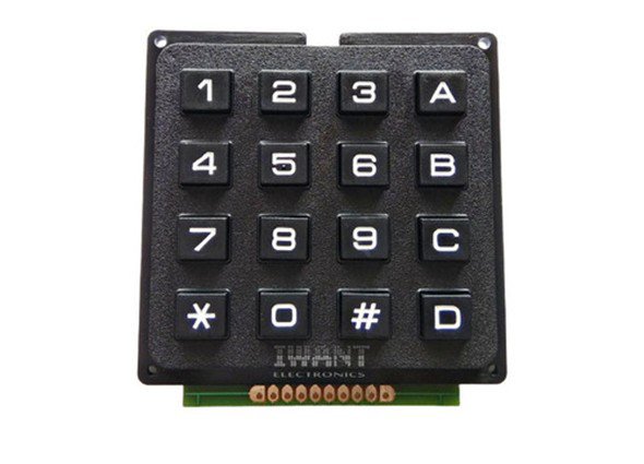
The Keypad-P is a versatile input device featuring push-button switches arranged in a matrix layout. It is commonly used for inputting data or commands into electronic devices. The matrix design allows for efficient key arrangement, reducing the number of microcontroller pins required for interfacing. Keypad-P is widely used in applications such as security systems, calculators, home automation, and embedded systems where user input is required.

Explore Projects Built with keypad-p

Use Cirkit Designer to design, explore, and prototype these projects online. Some projects support real-time simulation. Click "Open Project" to start designing instantly!
Arduino UNO Keypad-Controlled LED and Buzzer System with RTC and Bluetooth
Image of Uni: A project utilizing keypad-p in a practical application
This circuit is an Arduino-based keypad interface system that reads input from a 4x4 membrane matrix keypad and displays the pressed key on the serial monitor. It also includes a real-time clock (RTC) module, a Bluetooth module, and visual indicators using red and green LEDs. Additionally, a buzzer is controlled via an NPN transistor for audio feedback.
Cirkit Designer LogoOpen Project in Cirkit Designer
ESP32-Based Password-Protected Relay Control with 4x4 Keypad
Image of em lock: A project utilizing keypad-p in a practical application
This circuit is a password-protected relay control system using an ESP32 microcontroller and a 4x4 keypad. The user inputs an 8-digit password via the keypad, and if the password is correct, the ESP32 triggers a relay to activate a connected device. The system includes visual feedback through orange and green LEDs to indicate the relay's state.
Cirkit Designer LogoOpen Project in Cirkit Designer
Arduino UNO Membrane Keypad Interface
Image of Connect Adafruit 3x4 Matrix Keypad to Arduino Uno: A project utilizing keypad-p in a practical application
This circuit connects a 3x4 membrane matrix keypad to an Arduino UNO microcontroller. The Arduino is programmed to detect and report keypress events from the keypad over a serial connection at a baud rate of 9600. The purpose of this circuit is to interface with the keypad and provide a way to input data into a system or control a device.
Cirkit Designer LogoOpen Project in Cirkit Designer
Arduino Mega 2560 Controlled Relay Switch for PTC Air Heater
Image of ptc air heater functional test: A project utilizing keypad-p in a practical application
This circuit features an Arduino Mega 2560 microcontroller connected to a 4x4 membrane matrix keypad and a 1-channel relay module. The Arduino is programmed to interact with the keypad inputs and control the relay, which switches an AC supply connected to a PTC air heater. The purpose of the circuit is likely to allow user input via the keypad to control the heating element, potentially for a temperature regulation system.
Cirkit Designer LogoOpen Project in Cirkit Designer

Explore Projects Built with keypad-p

Use Cirkit Designer to design, explore, and prototype these projects online. Some projects support real-time simulation. Click "Open Project" to start designing instantly!
Image of Uni: A project utilizing keypad-p in a practical application
Arduino UNO Keypad-Controlled LED and Buzzer System with RTC and Bluetooth
This circuit is an Arduino-based keypad interface system that reads input from a 4x4 membrane matrix keypad and displays the pressed key on the serial monitor. It also includes a real-time clock (RTC) module, a Bluetooth module, and visual indicators using red and green LEDs. Additionally, a buzzer is controlled via an NPN transistor for audio feedback.
Cirkit Designer LogoOpen Project in Cirkit Designer
Image of em lock: A project utilizing keypad-p in a practical application
ESP32-Based Password-Protected Relay Control with 4x4 Keypad
This circuit is a password-protected relay control system using an ESP32 microcontroller and a 4x4 keypad. The user inputs an 8-digit password via the keypad, and if the password is correct, the ESP32 triggers a relay to activate a connected device. The system includes visual feedback through orange and green LEDs to indicate the relay's state.
Cirkit Designer LogoOpen Project in Cirkit Designer
Image of Connect Adafruit 3x4 Matrix Keypad to Arduino Uno: A project utilizing keypad-p in a practical application
Arduino UNO Membrane Keypad Interface
This circuit connects a 3x4 membrane matrix keypad to an Arduino UNO microcontroller. The Arduino is programmed to detect and report keypress events from the keypad over a serial connection at a baud rate of 9600. The purpose of this circuit is to interface with the keypad and provide a way to input data into a system or control a device.
Cirkit Designer LogoOpen Project in Cirkit Designer
Image of ptc air heater functional test: A project utilizing keypad-p in a practical application
Arduino Mega 2560 Controlled Relay Switch for PTC Air Heater
This circuit features an Arduino Mega 2560 microcontroller connected to a 4x4 membrane matrix keypad and a 1-channel relay module. The Arduino is programmed to interact with the keypad inputs and control the relay, which switches an AC supply connected to a PTC air heater. The purpose of the circuit is likely to allow user input via the keypad to control the heating element, potentially for a temperature regulation system.
Cirkit Designer LogoOpen Project in Cirkit Designer

Technical Specifications

  • Type: Matrix keypad
  • Number of Keys: Typically 4x4 (16 keys) or 4x3 (12 keys)
  • Operating Voltage: 3.3V to 5V
  • Current Consumption: < 10mA
  • Keypad Material: Plastic or rubber with conductive pads
  • Interface: Row and column pins for matrix scanning
  • Debouncing: Required in software or hardware for reliable operation

Pin Configuration and Descriptions

The Keypad-P typically has 7 or 8 pins, depending on the matrix size. Below is the pin configuration for a 4x4 keypad:

Pin Name Description
1 Row 1 (R1) First row of the keypad matrix
2 Row 2 (R2) Second row of the keypad matrix
3 Row 3 (R3) Third row of the keypad matrix
4 Row 4 (R4) Fourth row of the keypad matrix
5 Column 1 (C1) First column of the keypad matrix
6 Column 2 (C2) Second column of the keypad matrix
7 Column 3 (C3) Third column of the keypad matrix
8 Column 4 (C4) Fourth column of the keypad matrix (4x4 only)

For a 4x3 keypad, the last column pin (C4) is omitted.

Usage Instructions

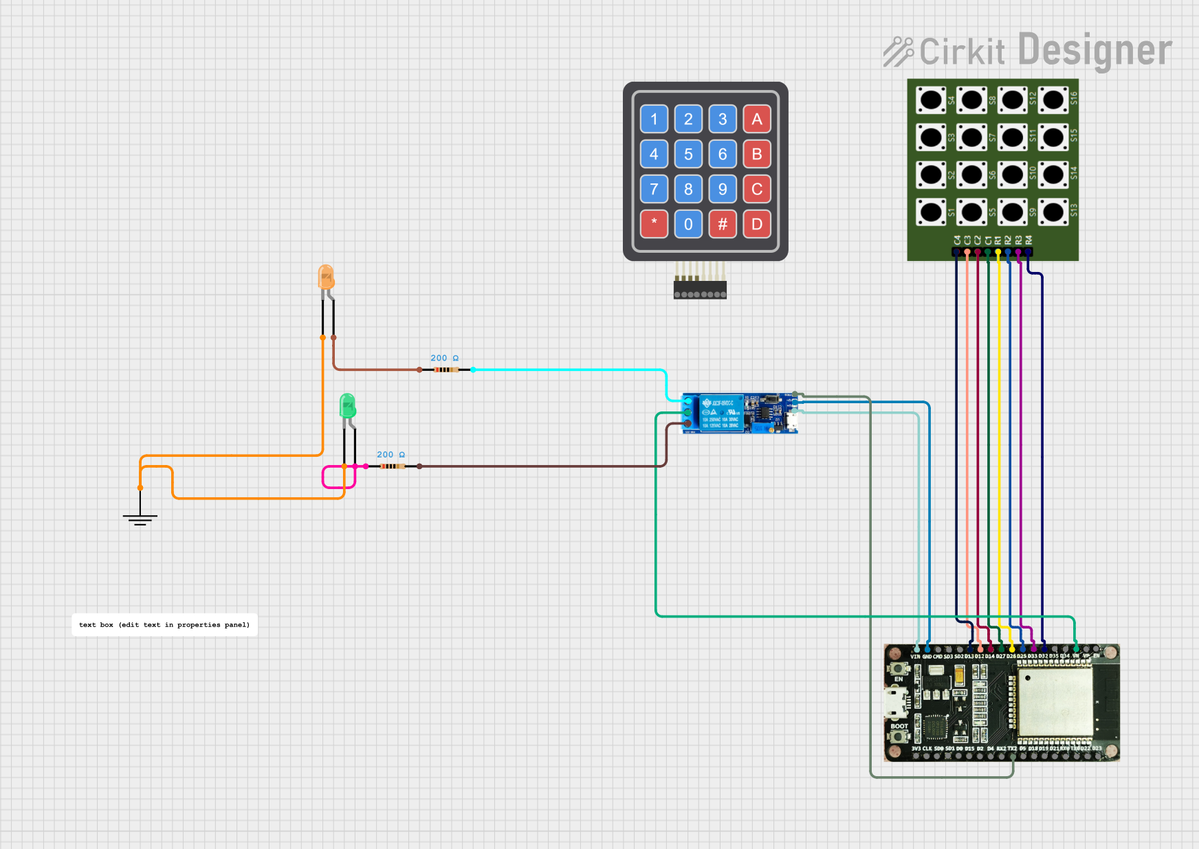
How to Use the Keypad-P in a Circuit

  1. Connect the Keypad to a Microcontroller:

    • Connect the row pins (R1-R4) and column pins (C1-C4) to the GPIO pins of your microcontroller.
    • Use pull-up or pull-down resistors if required by your microcontroller.
  2. Matrix Scanning:

    • The microcontroller scans the keypad by setting one row pin HIGH at a time and reading the column pins to detect which button is pressed.
  3. Debouncing:

    • Implement software debouncing to filter out false keypresses caused by mechanical vibrations.
  4. Power Supply:

    • Ensure the keypad operates within its voltage range (3.3V to 5V).

Important Considerations and Best Practices

  • Avoid Ghosting: Use diodes in the matrix if multiple keys are pressed simultaneously to prevent ghosting.
  • Use a Keypad Library: For Arduino and similar platforms, use a library like Keypad.h to simplify interfacing.
  • Secure Connections: Ensure all connections are firm to avoid intermittent keypress detection.

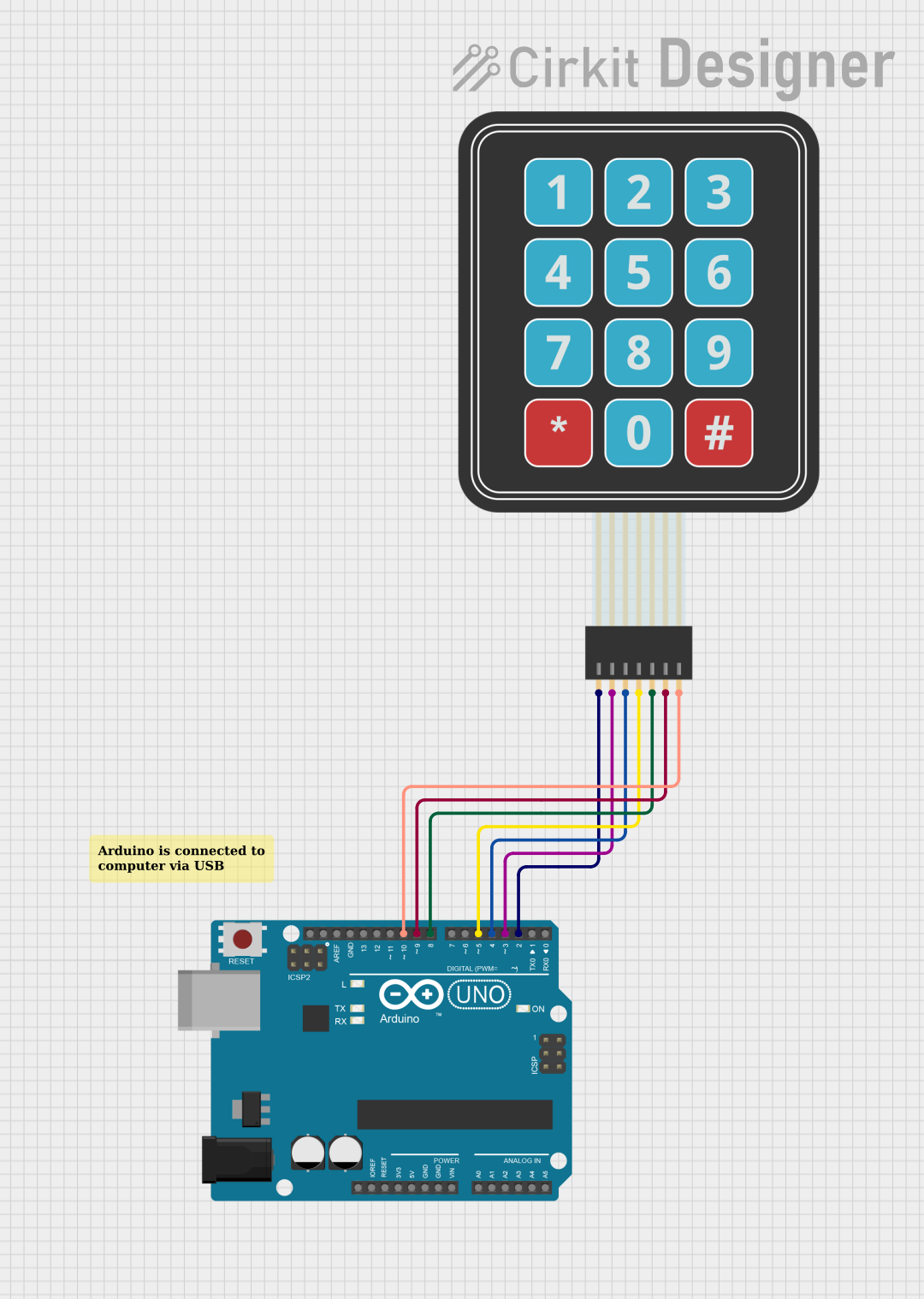
Example: Using Keypad-P with Arduino UNO

Below is an example of interfacing a 4x4 Keypad-P with an Arduino UNO:

#include <Keypad.h>

// Define the rows and columns of the keypad
const byte ROWS = 4; // Four rows
const byte COLS = 4; // Four columns

// Define the keymap for the keypad
char keys[ROWS][COLS] = {
  {'1', '2', '3', 'A'},
  {'4', '5', '6', 'B'},
  {'7', '8', '9', 'C'},
  {'*', '0', '#', 'D'}
};

// Define the row and column pins connected to the Arduino
byte rowPins[ROWS] = {9, 8, 7, 6}; // Connect to R1, R2, R3, R4
byte colPins[COLS] = {5, 4, 3, 2}; // Connect to C1, C2, C3, C4

// Create a Keypad object
Keypad keypad = Keypad(makeKeymap(keys), rowPins, colPins, ROWS, COLS);

void setup() {
  Serial.begin(9600); // Initialize serial communication
  Serial.println("Keypad Test: Press a key");
}

void loop() {
  char key = keypad.getKey(); // Get the key pressed
  if (key) {
    Serial.print("Key Pressed: ");
    Serial.println(key); // Print the key to the serial monitor
  }
}

Notes:

  • Ensure the row and column pins in the code match your hardware connections.
  • Use the serial monitor to view the keypresses.

Troubleshooting and FAQs

Common Issues and Solutions

  1. No Keypress Detected:

    • Check the wiring between the keypad and the microcontroller.
    • Verify that the row and column pins are correctly defined in the code.
  2. Multiple Keys Detected (Ghosting):

    • Add diodes to the matrix to prevent ghosting.
    • Ensure only one key is pressed at a time during testing.
  3. Unstable Keypresses:

    • Implement software debouncing to filter out noise.
    • Check for loose connections or faulty keypad hardware.
  4. Incorrect Key Mapping:

    • Verify the keymap in the code matches the physical layout of the keypad.

FAQs

Q: Can I use the Keypad-P with a 3.3V microcontroller?
A: Yes, the Keypad-P operates within a voltage range of 3.3V to 5V.

Q: How do I handle multiple simultaneous keypresses?
A: Use diodes in the matrix to prevent ghosting, or limit the application to single keypress detection.

Q: Is a library necessary to use the Keypad-P?
A: While not mandatory, using a library like Keypad.h simplifies the implementation and reduces development time.

Q: Can I use the Keypad-P for password input?
A: Yes, the Keypad-P is ideal for password input in security systems. Combine it with a microcontroller and appropriate logic to handle password verification.

By following this documentation, you can effectively integrate the Keypad-P into your projects for reliable and efficient user input.