How to Use EL817: Examples, Pinouts, and Specs
Introduction
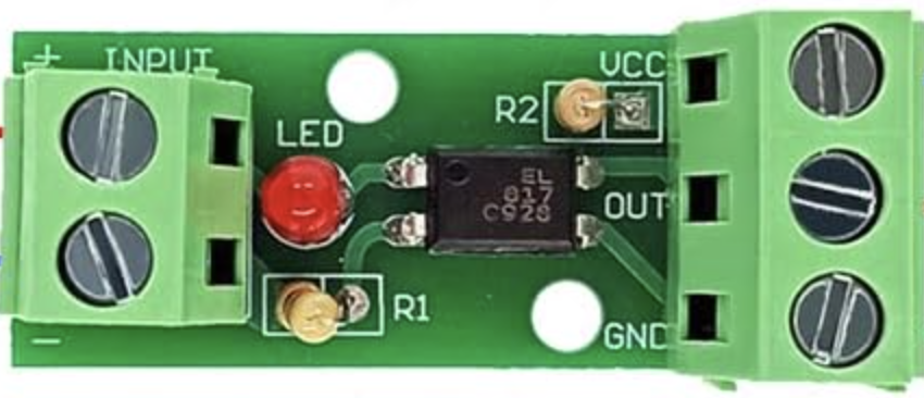
The EL817 is an optocoupler designed to provide electrical isolation between its input and output. It consists of an internal light-emitting diode (LED) and a phototransistor, enabling signal transmission without direct electrical connection. This isolation is crucial in protecting sensitive components from high voltages, noise, or ground loops in electronic circuits.
Explore Projects Built with EL817
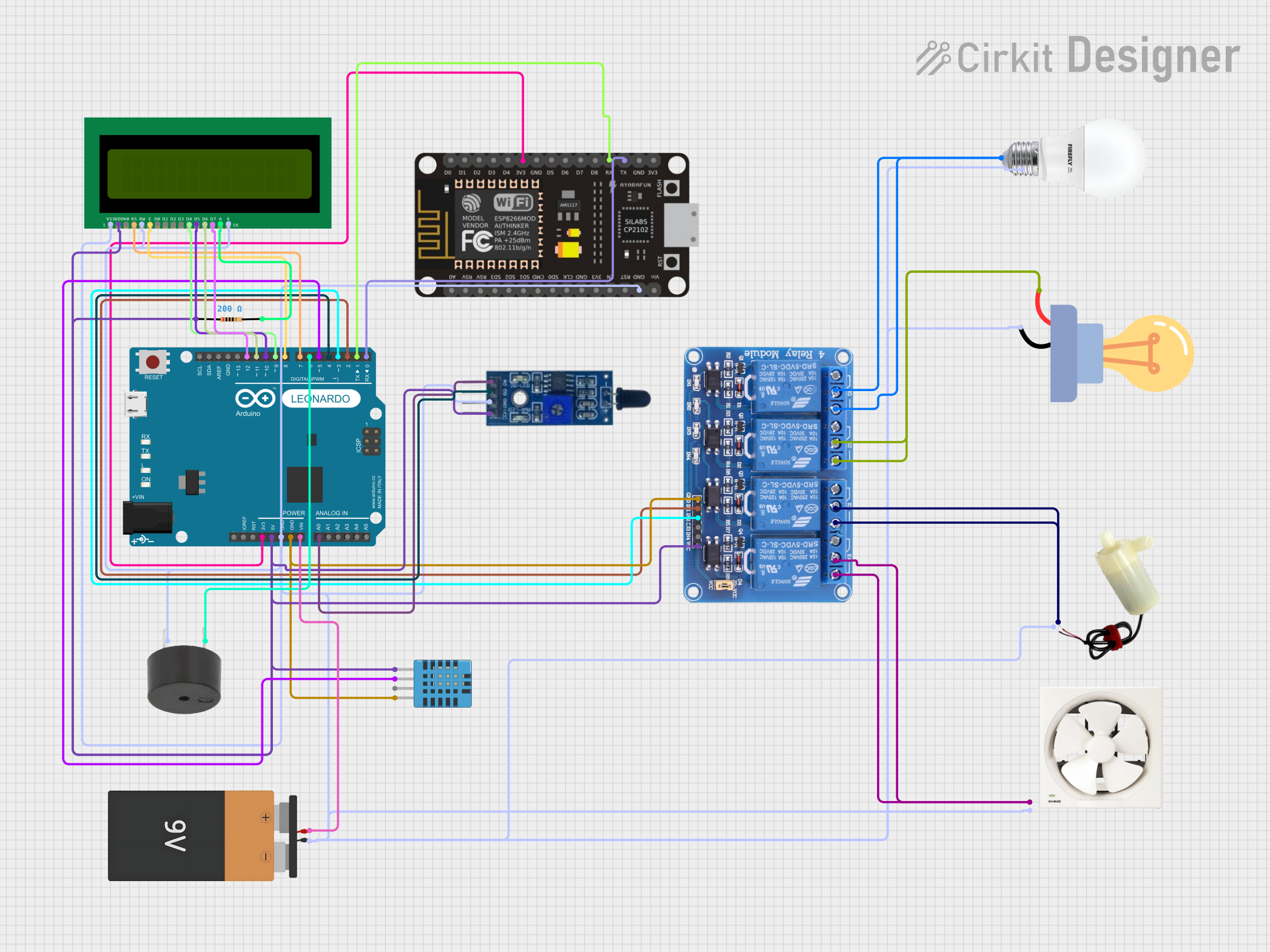
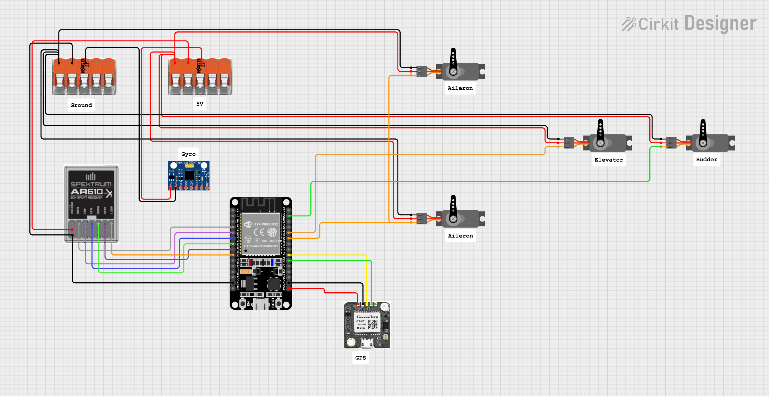
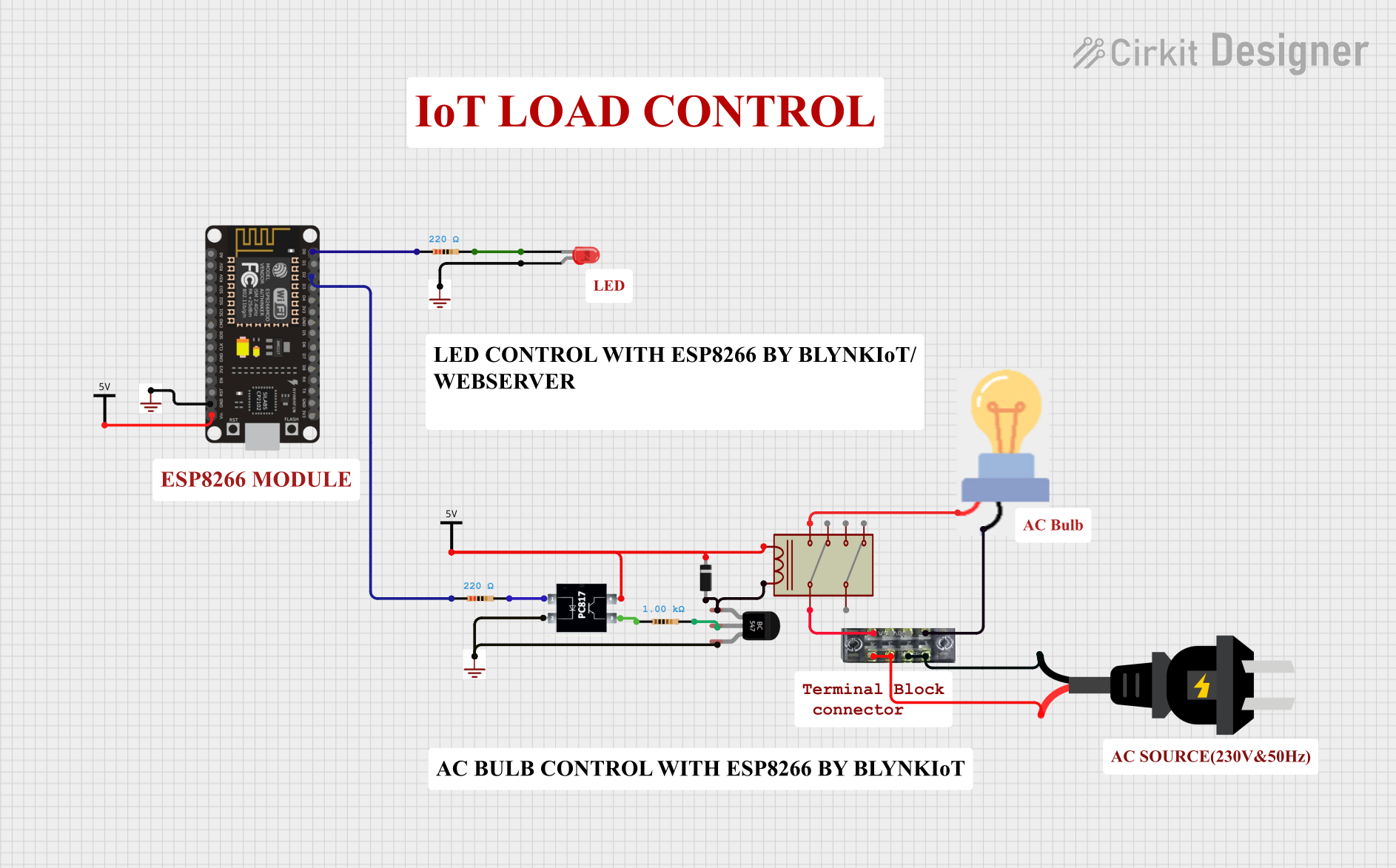
Explore Projects Built with EL817
Common Applications and Use Cases
- Signal isolation in microcontroller circuits
- Protection of low-voltage devices from high-voltage systems
- Noise suppression in industrial control systems
- Switching power supplies
- Data communication between systems with different ground potentials
Technical Specifications
Key Technical Details
| Parameter | Value |
|---|---|
| Input Forward Voltage (VF) | 1.2V (typical), 1.4V (maximum) |
| Input Forward Current (IF) | 20mA (typical), 50mA (maximum) |
| Output Collector-Emitter Voltage (VCEO) | 35V (maximum) |
| Output Collector Current (IC) | 50mA (maximum) |
| Isolation Voltage | 5000Vrms |
| Current Transfer Ratio (CTR) | 50% to 600% (depending on model) |
| Operating Temperature Range | -30°C to +100°C |
Pin Configuration and Descriptions
The EL817 is typically available in a 4-pin DIP (Dual Inline Package). Below is the pinout and description:
| Pin Number | Name | Description |
|---|---|---|
| 1 | Anode (A) | Positive terminal of the internal LED |
| 2 | Cathode (K) | Negative terminal of the internal LED |
| 3 | Emitter (E) | Emitter of the internal phototransistor |
| 4 | Collector (C) | Collector of the internal phototransistor |
Usage Instructions
How to Use the EL817 in a Circuit
Input Side (LED):
- Connect the anode (Pin 1) to a current-limiting resistor and then to the input signal source.
- Connect the cathode (Pin 2) to the ground of the input circuit.
- Ensure the forward current (IF) does not exceed 50mA to avoid damaging the LED.
Output Side (Phototransistor):
- Connect the collector (Pin 4) to the positive voltage supply through a pull-up resistor.
- Connect the emitter (Pin 3) to the ground of the output circuit.
- The phototransistor will conduct when the LED is forward-biased, allowing signal transmission.
Important Considerations and Best Practices
- Current Transfer Ratio (CTR): Ensure the CTR of the EL817 matches the requirements of your circuit. CTR varies with input current and temperature.
- Isolation Voltage: Verify that the isolation voltage (5000Vrms) is sufficient for your application.
- Resistor Selection: Use appropriate resistors to limit current on both the input and output sides.
- Temperature Range: Operate the EL817 within its specified temperature range (-30°C to +100°C) to ensure reliable performance.
Example: Connecting EL817 to an Arduino UNO
The EL817 can be used to isolate an Arduino UNO from a high-voltage circuit. Below is an example of how to connect it:
Circuit Diagram
- Input Side: Connect the anode (Pin 1) to an Arduino digital pin (e.g., D3) through a 220Ω resistor. Connect the cathode (Pin 2) to the Arduino ground.
- Output Side: Connect the collector (Pin 4) to a 5V supply through a 10kΩ pull-up resistor. Connect the emitter (Pin 3) to the ground of the high-voltage circuit.
Arduino Code
// Example code to control the EL817 optocoupler with an Arduino UNO

const int optoPin = 3; // Pin connected to the EL817 anode through a resistor

void setup() {
  pinMode(optoPin, OUTPUT); // Set the optoPin as an output
}

void loop() {
  digitalWrite(optoPin, HIGH); // Turn on the LED inside the EL817
  delay(1000);                // Wait for 1 second
  digitalWrite(optoPin, LOW);  // Turn off the LED
  delay(1000);                // Wait for 1 second
}
Troubleshooting and FAQs
Common Issues and Solutions
No Signal Transmission:
- Cause: Insufficient input current to the LED.
- Solution: Check the input resistor value and ensure the forward current (IF) is within the recommended range (typically 10-20mA).
Output Signal is Weak or Unstable:
- Cause: Incorrect pull-up resistor value on the output side.
- Solution: Use a pull-up resistor between 4.7kΩ and 10kΩ, depending on the circuit requirements.
Component Overheating:
- Cause: Excessive input current or output current.
- Solution: Verify that the input and output currents are within the specified limits.
Isolation Failure:
- Cause: Exceeding the isolation voltage rating.
- Solution: Ensure the voltage difference between input and output does not exceed 5000Vrms.
FAQs
Q1: Can the EL817 be used for AC signal isolation?
A1: Yes, the EL817 can isolate AC signals, but you may need additional circuitry (e.g., a rectifier) to handle bidirectional signals.
Q2: What is the typical lifespan of the EL817?
A2: The EL817 has a long operational lifespan when used within its specified ratings. However, excessive current or temperature can reduce its lifespan.
Q3: Can I use the EL817 for high-speed signal transmission?
A3: The EL817 is suitable for low- to medium-speed signals. For high-speed applications, consider optocouplers designed for faster response times.
Q4: How do I calculate the input resistor value?
A4: Use Ohm's Law: ( R = \frac{V_{in} - V_F}{I_F} ), where ( V_{in} ) is the input voltage, ( V_F ) is the forward voltage (1.2V typical), and ( I_F ) is the desired forward current (e.g., 10mA).