How to Use RS485 V2: Examples, Pinouts, and Specs
Introduction
RS485 V2 is a standard for serial communication that enables reliable, long-distance data transmission. It supports multiple devices on a single bus, making it ideal for multi-point communication systems. RS485 V2 is widely used in industrial applications due to its robustness, noise immunity, and ability to operate in harsh environments. It is particularly suited for scenarios where data integrity and communication over extended distances are critical.
Explore Projects Built with RS485 V2


Explore Projects Built with RS485 V2
Common Applications and Use Cases
- Industrial automation and control systems
- Building management systems (e.g., HVAC, lighting control)
- Data acquisition systems
- Communication between microcontrollers and sensors
- Long-distance serial communication in noisy environments
Technical Specifications
Key Technical Details
- Communication Standard: RS485
- Voltage Levels: Differential signaling, typically ±5V
- Maximum Bus Length: Up to 1200 meters (4000 feet)
- Maximum Data Rate: 10 Mbps (short distances), reduced at longer distances
- Number of Devices: Supports up to 32 devices on a single bus
- Connector Type: Terminal block or DB9 (varies by module)
- Power Supply: Typically 5V or 3.3V (check specific module requirements)
- Operating Temperature: -40°C to +85°C (varies by module)
Pin Configuration and Descriptions
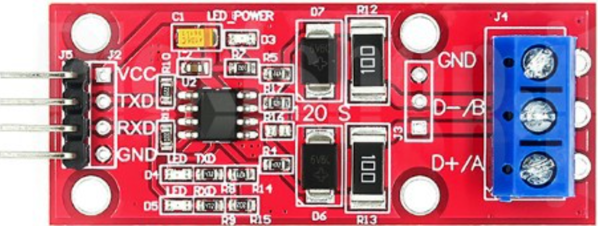
Below is a typical pinout for an RS485 V2 module:
| Pin Name | Description |
|---|---|
| VCC | Power supply input (typically 5V or 3.3V). |
| GND | Ground connection. |
| A (D+) | Non-inverting differential signal line (positive data line). |
| B (D-) | Inverting differential signal line (negative data line). |
| RO | Receiver output (data received from the RS485 bus). |
| DI | Driver input (data to be transmitted onto the RS485 bus). |
| DE | Driver enable (controls whether the module is transmitting or receiving). |
| RE | Receiver enable (active low, enables the receiver when pulled low). |
Note: Pin names and configurations may vary slightly depending on the specific RS485 V2 module. Always refer to the datasheet for your module.
Usage Instructions
How to Use the RS485 V2 in a Circuit
- Power the Module: Connect the VCC pin to a 5V or 3.3V power source (as required by your module) and the GND pin to the ground of your circuit.
- Connect the Differential Lines: Connect the A (D+) and B (D-) pins to the corresponding lines of the RS485 bus.
- Control the Module:
- Use the DE pin to enable the driver (set high to transmit data).
- Use the RE pin to enable the receiver (set low to receive data).
- Interface with a Microcontroller:
- Connect the DI pin to the microcontroller's TX (transmit) pin.
- Connect the RO pin to the microcontroller's RX (receive) pin.
- Termination Resistor: For long-distance communication, add a 120-ohm termination resistor across the A and B lines at both ends of the bus to prevent signal reflections.
Important Considerations and Best Practices
- Bus Topology: Use a daisy-chain topology for the RS485 bus. Avoid star or ring configurations.
- Grounding: Ensure all devices on the RS485 bus share a common ground to prevent communication errors.
- Line Biasing: Use pull-up and pull-down resistors on the A and B lines to maintain a known idle state when no devices are transmitting.
- Noise Immunity: Use twisted-pair cables for the A and B lines to reduce electromagnetic interference (EMI).
- Device Addressing: Assign unique addresses to each device on the bus for proper communication.
Example: Connecting RS485 V2 to an Arduino UNO
Below is an example of how to connect and use the RS485 V2 module with an Arduino UNO:
Circuit Connections
- RS485 V2 Module:
- VCC → 5V on Arduino
- GND → GND on Arduino
- DI → Pin 3 (TX) on Arduino
- RO → Pin 2 (RX) on Arduino
- DE → Pin 4 on Arduino
- RE → Pin 4 on Arduino (tied to DE for simplicity)
Arduino Code
// RS485 V2 Example Code for Arduino UNO
// This code demonstrates basic communication using the RS485 V2 module.

#define DE_RE_PIN 4  // Pin connected to DE and RE on the RS485 module
#define TX_PIN 3     // Arduino TX pin connected to DI on the RS485 module
#define RX_PIN 2     // Arduino RX pin connected to RO on the RS485 module

void setup() {
  pinMode(DE_RE_PIN, OUTPUT);  // Set DE/RE pin as output
  digitalWrite(DE_RE_PIN, LOW); // Set to receive mode initially

  Serial.begin(9600);          // Initialize serial communication
  Serial.println("RS485 V2 Communication Initialized");
}

void loop() {
  // Transmit data
  digitalWrite(DE_RE_PIN, HIGH); // Enable transmit mode
  delay(10);                     // Small delay to stabilize
  Serial.println("Hello, RS485!"); // Send data
  delay(10);                     // Small delay to ensure data is sent
  digitalWrite(DE_RE_PIN, LOW);  // Switch back to receive mode

  // Receive data (if any)
  if (Serial.available()) {
    String receivedData = Serial.readString();
    Serial.print("Received: ");
    Serial.println(receivedData);
  }

  delay(1000); // Wait 1 second before next transmission
}
Note: Ensure that the baud rate and communication settings match across all devices on the RS485 bus.
Troubleshooting and FAQs
Common Issues and Solutions
No Communication Between Devices:
- Verify that the A and B lines are correctly connected (A to A, B to B).
- Check the DE and RE pin states to ensure the module is in the correct mode (transmit or receive).
- Ensure all devices share a common ground.
Data Corruption or Noise:
- Use twisted-pair cables for the A and B lines.
- Add a 120-ohm termination resistor at both ends of the RS485 bus.
- Check for proper line biasing with pull-up and pull-down resistors.
Limited Communication Range:
- Reduce the baud rate for longer distances.
- Ensure the cable length does not exceed 1200 meters.
Multiple Devices Not Responding:
- Verify that each device has a unique address.
- Check for bus contention (only one device should transmit at a time).
FAQs
Q: Can RS485 V2 communicate with RS232 devices?
A: No, RS485 and RS232 use different signaling methods. You will need an RS485-to-RS232 converter for compatibility.
Q: How many devices can I connect to an RS485 bus?
A: RS485 supports up to 32 devices on a single bus. However, some modern transceivers allow for more devices.
Q: Can I use RS485 V2 for wireless communication?
A: RS485 is a wired communication standard. For wireless communication, consider using modules like Zigbee or LoRa.
Q: Do I need termination resistors for short distances?
A: Termination resistors are generally not required for short distances, but they are recommended for long-distance communication to prevent signal reflections.