How to Use fan motor L9110: Examples, Pinouts, and Specs
Introduction
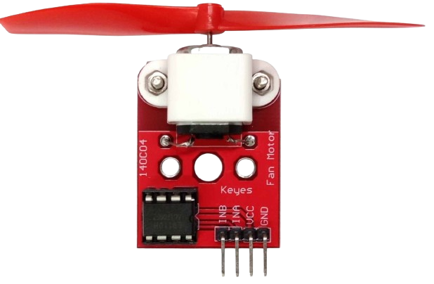
The L9110 fan motor driver is an integrated circuit designed to control small DC motors, particularly for applications requiring speed and direction control. It is widely used in robotics, hobby projects, and small fan systems. The L9110 can drive a single motor in both clockwise and anticlockwise directions with Pulse Width Modulation (PWM) speed control, making it a versatile choice for various low-voltage motor control applications.
Explore Projects Built with fan motor L9110
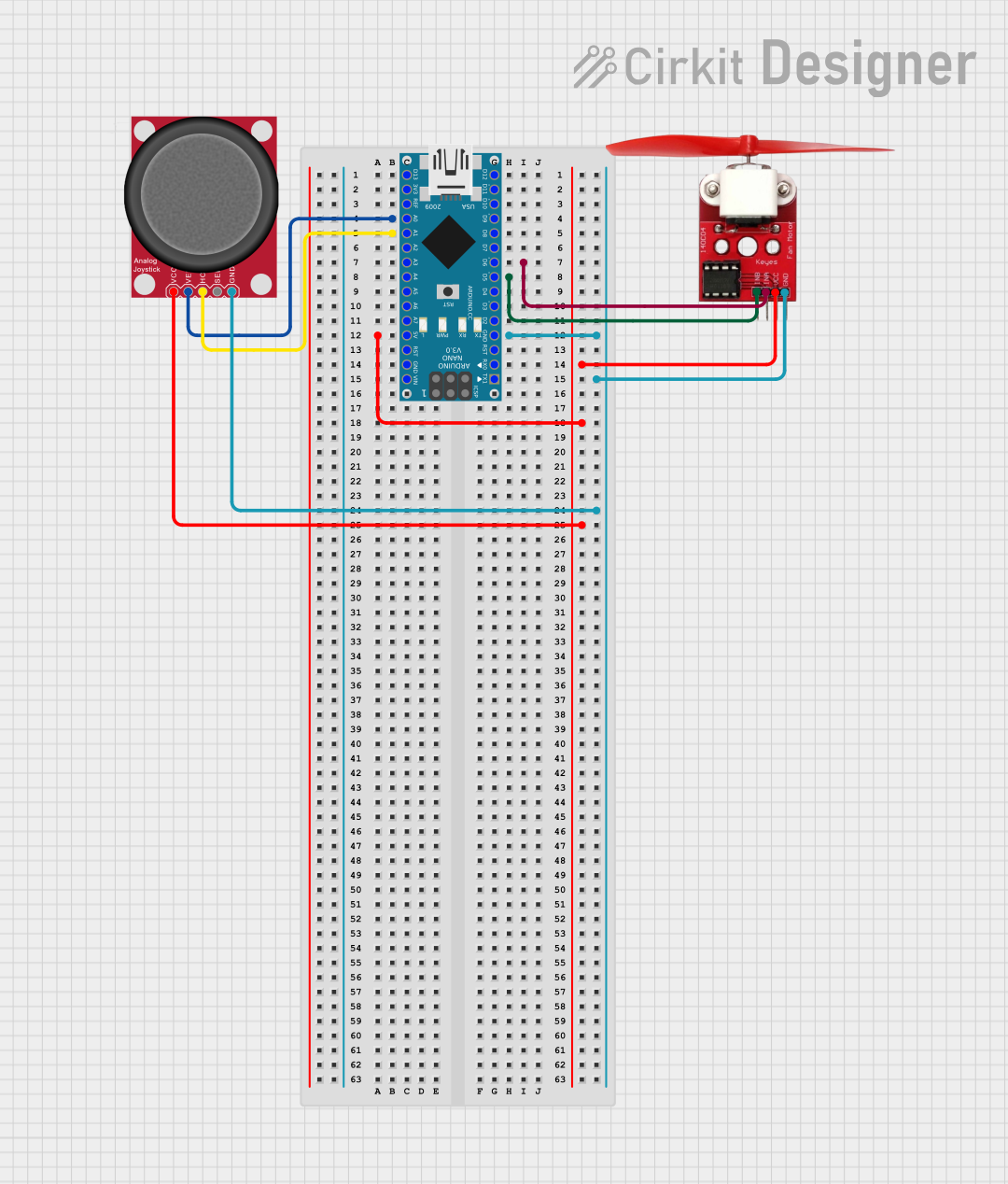

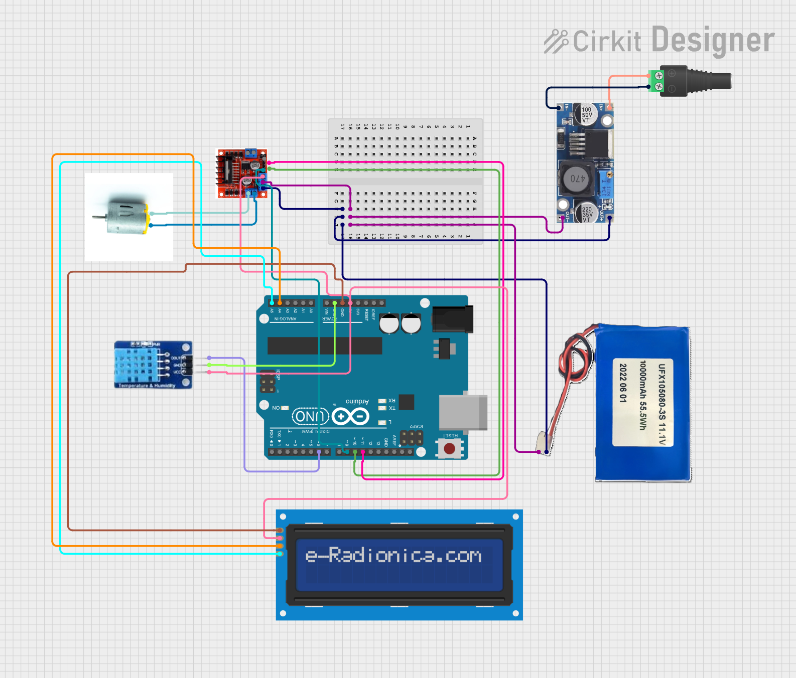

Explore Projects Built with fan motor L9110
Technical Specifications
Key Technical Details
- Operating Voltage: 2.5V to 12V
- Output Current: Up to 800mA per channel
- Control Inputs: TTL/CMOS compatible
- PWM Control: Yes
- Operating Temperature: -25°C to +125°C
Pin Configuration and Descriptions
| Pin Number | Pin Name | Description |
|---|---|---|
| 1 | Vcc | Power supply for the IC (2.5V to 12V) |
| 2 | GND | Ground |
| 3 | IA | Input A, controls motor direction |
| 4 | IB | Input B, controls motor direction |
| 5 | OA | Output A, connects to one motor terminal |
| 6 | OB | Output B, connects to other motor terminal |
Usage Instructions
Connecting the L9110 to a Circuit
- Connect the Vcc pin to your power supply (2.5V to 12V).
- Connect the GND pin to the ground of your power supply.
- Connect the motor terminals to the OA and OB pins.
- Connect the control inputs (IA and IB) to your microcontroller or control circuitry.
Controlling Motor Speed and Direction
- To control the direction, set IA and IB to different logic levels:
- IA = HIGH and IB = LOW for clockwise rotation.
- IA = LOW and IB = HIGH for anticlockwise rotation.
- To control the speed, apply a PWM signal to either IA or IB while keeping the other pin at a constant logic level.
Best Practices
- Use a decoupling capacitor close to the Vcc and GND pins to minimize power supply noise.
- Ensure that the motor current does not exceed the maximum rating of 800mA.
- Avoid running the IC at the maximum voltage and current simultaneously to prevent overheating.
Example Code for Arduino UNO
// Define L9110 control pins
const int motorIA = 3; // Connect to IA on L9110
const int motorIB = 5; // Connect to IB on L9110

void setup() {
  // Set motor control pins as outputs
  pinMode(motorIA, OUTPUT);
  pinMode(motorIB, OUTPUT);
}

void loop() {
  // Set motor to rotate clockwise
  analogWrite(motorIA, 255); // Full speed
  digitalWrite(motorIB, LOW);
  delay(2000); // Run for 2 seconds

  // Set motor to rotate anticlockwise
  digitalWrite(motorIA, LOW);
  analogWrite(motorIB, 255); // Full speed
  delay(2000); // Run for 2 seconds

  // Stop the motor
  digitalWrite(motorIA, LOW);
  digitalWrite(motorIB, LOW);
  delay(1000); // Stop for 1 second
}
Troubleshooting and FAQs
Common Issues
- Motor not spinning: Check connections, ensure power supply is within the specified range, and verify that the control inputs are receiving the correct signals.
- Motor spinning slowly or weakly: Ensure the power supply can deliver sufficient current, and check for any voltage drops.
- IC overheating: Reduce the load on the motor or improve heat dissipation with a heatsink.
FAQs
Q: Can I control two motors with one L9110 IC? A: No, the L9110 is designed to control one motor. For two motors, you would need two L9110 ICs or a dual-channel motor driver.
Q: What is the maximum PWM frequency for the L9110? A: The L9110 can typically handle PWM frequencies up to 100kHz, but for most applications, a frequency between 1kHz and 10kHz is sufficient.
Q: Can I use the L9110 without PWM for simple on/off control? A: Yes, you can use the L9110 without PWM by providing a high or low signal to the control inputs for on/off control.
Remember to always consult the L9110 datasheet for the most accurate and detailed information regarding the component's capabilities and limitations.