How to Use Arduino Nano ESP32: Examples, Pinouts, and Specs
Introduction
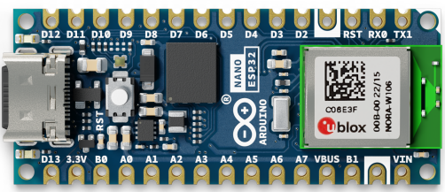
The Arduino Nano ESP32 is a compact microcontroller board developed by Arduino, combining the familiar form factor of the Arduino Nano with the powerful ESP32 chip. This board offers built-in Wi-Fi and Bluetooth connectivity, making it an excellent choice for Internet of Things (IoT) applications, wireless communication, and smart devices. Its small size and versatile features make it suitable for both beginners and advanced users.
Explore Projects Built with Arduino Nano ESP32
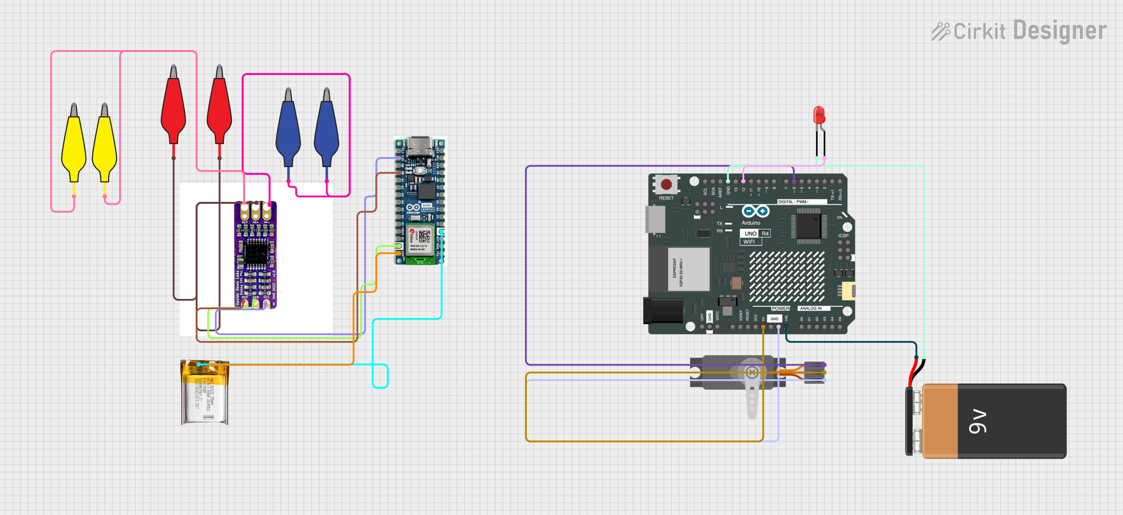
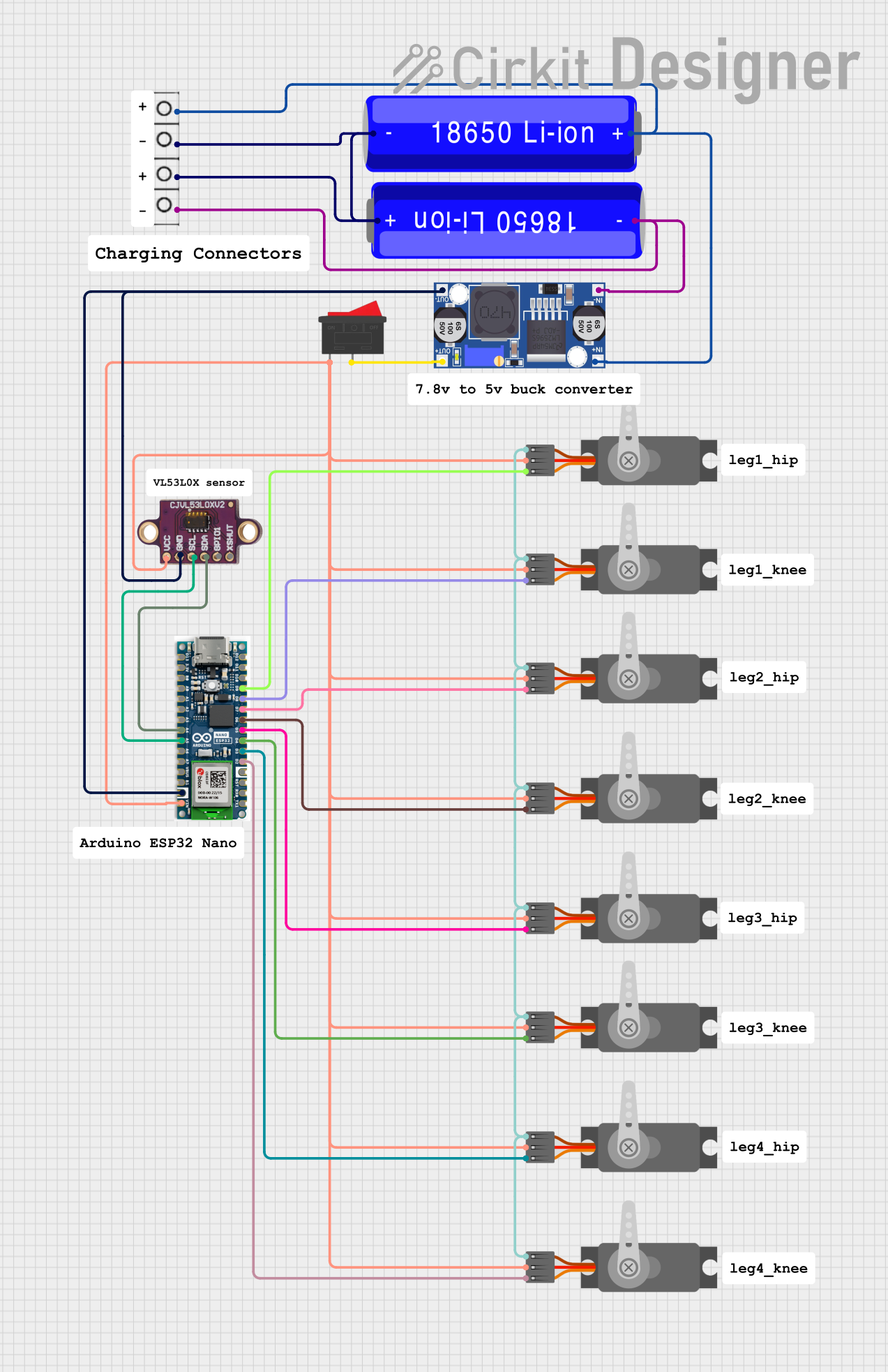
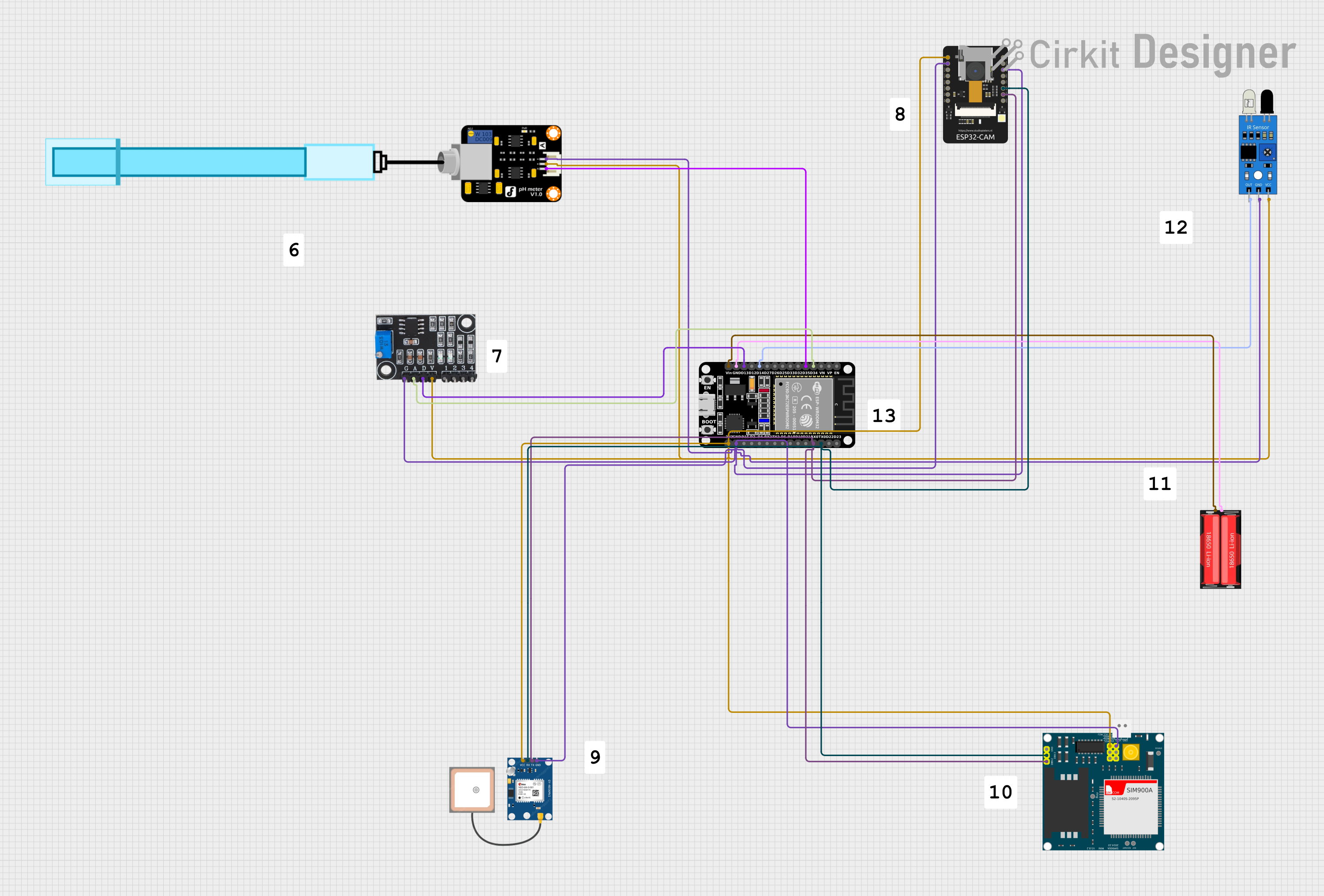
Explore Projects Built with Arduino Nano ESP32
Common Applications and Use Cases
- IoT devices and smart home automation
- Wireless sensor networks
- Remote data logging and monitoring
- Bluetooth-enabled devices
- Robotics and wearable technology
- Prototyping and educational projects
Technical Specifications
The following table outlines the key technical details of the Arduino Nano ESP32:
| Specification | Details |
|---|---|
| Microcontroller | ESP32-S3 |
| Operating Voltage | 3.3V |
| Input Voltage (VIN) | 5V (via USB or VIN pin) |
| Digital I/O Pins | 14 |
| Analog Input Pins | 8 |
| PWM Pins | 14 |
| Flash Memory | 16 MB |
| SRAM | 512 KB |
| Clock Speed | 240 MHz |
| Connectivity | Wi-Fi 802.11 b/g/n, Bluetooth 5.0 |
| USB Interface | USB-C |
| Dimensions | 45 x 18 mm |
| Weight | 5 g |
Pin Configuration and Descriptions
The Arduino Nano ESP32 features a 30-pin layout. Below is the pin configuration:
| Pin | Name | Description |
|---|---|---|
| 1 | VIN | Input voltage (5V) for powering the board. |
| 2 | GND | Ground pin. |
| 3 | 3V3 | 3.3V output pin. |
| 4-11 | D0-D7 | Digital I/O pins (can also be used for PWM). |
| 12-13 | RX, TX | UART communication pins. |
| 14-21 | A0-A7 | Analog input pins. |
| 22 | SDA | I2C data line. |
| 23 | SCL | I2C clock line. |
| 24 | RST | Reset pin. |
| 25-26 | GPIO21, GPIO22 | General-purpose I/O pins. |
| 27 | EN | Enable pin for the ESP32 chip. |
| 28-30 | USB D+, USB D- | USB data lines for programming and communication. |
Usage Instructions
How to Use the Arduino Nano ESP32 in a Circuit
Powering the Board:
- Use the USB-C port to power the board and upload code.
- Alternatively, supply 5V to the VIN pin for external power.
Programming the Board:
- Install the Arduino IDE and add the ESP32 board package via the Board Manager.
- Select "Arduino Nano ESP32" as the board type.
- Connect the board to your computer using a USB-C cable.
Connecting Peripherals:
- Use the digital and analog pins to connect sensors, actuators, and other peripherals.
- For I2C devices, connect to the SDA and SCL pins.
- For UART communication, use the RX and TX pins.
Wi-Fi and Bluetooth Setup:
- Use the ESP32 libraries in the Arduino IDE to configure Wi-Fi and Bluetooth.
- Example libraries:
WiFi.hfor Wi-Fi andBluetoothSerial.hfor Bluetooth.
Example Code: Wi-Fi Connection
The following example demonstrates how to connect the Arduino Nano ESP32 to a Wi-Fi network:
#include <WiFi.h> // Include the Wi-Fi library

const char* ssid = "Your_SSID";       // Replace with your Wi-Fi network name
const char* password = "Your_Password"; // Replace with your Wi-Fi password

void setup() {
  Serial.begin(115200); // Initialize serial communication at 115200 baud
  WiFi.begin(ssid, password); // Start Wi-Fi connection

  Serial.print("Connecting to Wi-Fi");
  while (WiFi.status() != WL_CONNECTED) {
    delay(500); // Wait for connection
    Serial.print(".");
  }
  Serial.println("\nConnected to Wi-Fi!");
  Serial.print("IP Address: ");
  Serial.println(WiFi.localIP()); // Print the assigned IP address
}

void loop() {
  // Add your main code here
}
Important Considerations and Best Practices
- Ensure the board is powered with a stable 5V supply to avoid instability.
- Avoid exceeding the maximum current ratings of the I/O pins (12 mA per pin).
- Use level shifters when interfacing with 5V logic devices, as the board operates at 3.3V.
- Always check the pinout diagram to avoid incorrect connections.
- Update the ESP32 board package in the Arduino IDE regularly for the latest features and bug fixes.
Troubleshooting and FAQs
Common Issues and Solutions
Problem: The board is not detected by the Arduino IDE.
Solution:- Ensure the correct USB driver is installed for the ESP32.
- Check that the USB-C cable supports data transfer (not just charging).
- Select the correct COM port in the Arduino IDE.
Problem: Wi-Fi connection fails.
Solution:- Double-check the SSID and password.
- Ensure the Wi-Fi network is within range.
- Restart the board and router if necessary.
Problem: Code upload fails with an error.
Solution:- Press and hold the "BOOT" button on the board while uploading the code.
- Verify that the correct board and port are selected in the Arduino IDE.
Problem: The board overheats during operation.
Solution:- Avoid drawing excessive current from the I/O pins.
- Ensure proper ventilation and avoid placing the board in enclosed spaces.
FAQs
Q: Can I use the Arduino Nano ESP32 with 5V sensors?
A: Yes, but you will need a level shifter to convert the 5V signals to 3.3V.Q: Does the board support OTA (Over-The-Air) updates?
A: Yes, the ESP32 supports OTA updates. You can use theArduinoOTAlibrary to implement this feature.Q: What is the maximum range of the Wi-Fi and Bluetooth?
A: The Wi-Fi range is approximately 30 meters indoors and 100 meters outdoors. Bluetooth range depends on the environment but typically extends up to 10 meters.Q: Can I power the board directly with a LiPo battery?
A: Yes, you can use a LiPo battery with a 3.7V output, but ensure proper regulation to avoid damaging the board.
This concludes the documentation for the Arduino Nano ESP32. For further assistance, refer to the official Arduino documentation or community forums.