How to Use A9G: Examples, Pinouts, and Specs
A9G GSM/GPRS + GPS Module Documentation
1. Introduction
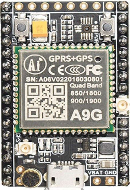
The A9G is a compact and versatile GSM/GPRS module with integrated GPS functionality, manufactured by AI-Thinker. It is designed for applications requiring cellular communication and location tracking, making it an ideal choice for IoT (Internet of Things) projects, asset tracking, vehicle monitoring, and remote control systems.
The A9G module supports quad-band GSM/GPRS communication, enabling it to send and receive data over cellular networks. Its built-in GPS functionality allows for precise location tracking, making it a powerful solution for applications that require both communication and geolocation capabilities.
Common Applications:
- IoT devices for remote monitoring and control
- GPS-based asset tracking systems
- Vehicle tracking and fleet management
- Smart agriculture and environmental monitoring
- Wearable devices with location tracking
- Emergency alert systems
2. Technical Specifications
The following table outlines the key technical specifications of the A9G module:
| Parameter | Specification |
|---|---|
| Manufacturer | AI-Thinker |
| Part ID | A9G |
| GSM Frequency Bands | Quad-band: 850/900/1800/1900 MHz |
| GPRS Connectivity | GPRS Class 10 |
| GPS Sensitivity | -165 dBm |
| GPS Positioning Accuracy | < 2.5 meters |
| Operating Voltage | 3.3V to 4.2V |
| Operating Current | Idle: ~3mA, Active: ~20-30mA, Peak: ~2A |
| Communication Interface | UART, I2C, SPI |
| Operating Temperature | -40°C to +85°C |
| Dimensions | 22mm x 20mm x 2.3mm |
Pin Configuration and Descriptions
The A9G module has 24 pins. Below is the pinout and description:
| Pin Number | Pin Name | Description |
|---|---|---|
| 1 | VCC | Power supply input (3.3V to 4.2V) |
| 2 | GND | Ground |
| 3 | TXD | UART Transmit (connect to RX of microcontroller) |
| 4 | RXD | UART Receive (connect to TX of microcontroller) |
| 5 | PWRKEY | Power key (active low, hold for 2 seconds to power on/off) |
| 6 | NETLIGHT | Network status indicator (blinks to indicate GSM/GPRS status) |
| 7 | GPS_TXD | GPS UART Transmit |
| 8 | GPS_RXD | GPS UART Receive |
| 9 | RESET | Reset pin (active low) |
| 10 | ANT_GSM | GSM antenna interface |
| 11 | ANT_GPS | GPS antenna interface |
| 12-24 | NC | Not connected (reserved for future use) |
3. Usage Instructions
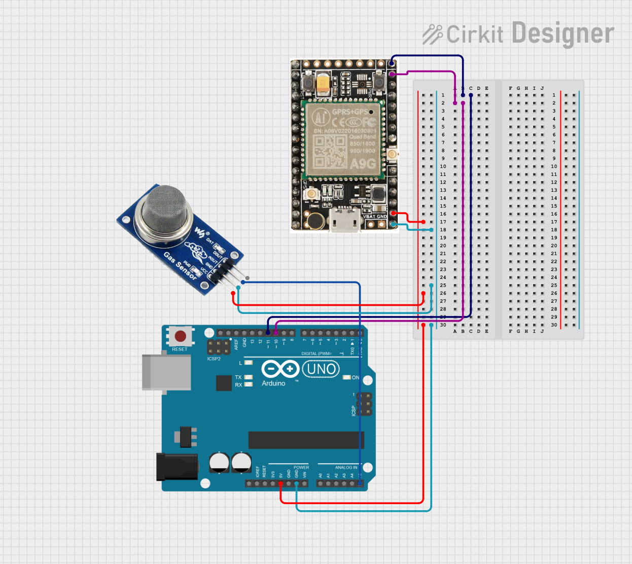
Connecting the A9G to an Arduino UNO
To use the A9G module with an Arduino UNO, follow these steps:
- Power Supply: Ensure the A9G module is powered with a stable voltage between 3.3V and 4.2V. Use an external power source capable of providing at least 2A for peak current requirements.
- UART Connection: Connect the A9G's
TXDpin to the Arduino'sRXpin (D0) and the A9G'sRXDpin to the Arduino'sTXpin (D1). - Power Key: Connect the
PWRKEYpin to GND for at least 2 seconds to power on the module. - Antenna: Attach a GSM antenna to the
ANT_GSMpin and a GPS antenna to theANT_GPSpin for proper signal reception. - Network Status: Monitor the
NETLIGHTpin to check the GSM/GPRS connection status.
Sample Arduino Code
The following example demonstrates how to send an SMS using the A9G module:
#include <SoftwareSerial.h>

// Define A9G module pins
#define A9G_TX 10  // Connect to A9G RXD
#define A9G_RX 11  // Connect to A9G TXD

// Create a SoftwareSerial instance for communication with A9G
SoftwareSerial A9G(A9G_TX, A9G_RX);

void setup() {
  // Initialize serial communication
  Serial.begin(9600);  // For debugging
  A9G.begin(9600);     // For A9G communication

  // Power on the A9G module
  Serial.println("Initializing A9G module...");
  delay(2000);  // Wait for the module to initialize

  // Send SMS
  sendSMS("+1234567890", "Hello from A9G module!");
}

void loop() {
  // Nothing to do here
}

void sendSMS(const char* phoneNumber, const char* message) {
  A9G.println("AT+CMGF=1");  // Set SMS mode to text
  delay(1000);

  A9G.print("AT+CMGS=\"");
  A9G.print(phoneNumber);    // Set recipient phone number
  A9G.println("\"");
  delay(1000);

  A9G.print(message);        // Write the SMS message
  delay(1000);

  A9G.write(26);             // Send Ctrl+Z to send the SMS
  delay(5000);

  Serial.println("SMS sent!");
}
Important Considerations:
- Use a dedicated power supply for the A9G module to avoid voltage drops.
- Ensure proper antenna placement for optimal GSM and GPS signal reception.
- Avoid using the Arduino's hardware UART (pins 0 and 1) for debugging when connected to the A9G.
4. Troubleshooting and FAQs
Common Issues and Solutions
| Issue | Possible Cause | Solution |
|---|---|---|
| Module does not power on | Insufficient power supply | Use a power source capable of providing at least 2A. |
| No GSM network connection | Poor signal or incorrect antenna connection | Check the GSM antenna and ensure proper placement in a signal-rich area. |
| GPS not working | GPS antenna not connected or poor signal | Attach a GPS antenna and ensure it has a clear view of the sky. |
| No response from the module | Incorrect UART connection | Verify TX and RX connections between the A9G and the microcontroller. |
| SMS not sent | Incorrect AT command or network issue | Double-check the AT commands and ensure the SIM card has sufficient balance. |
FAQs
Can the A9G module work with 5V logic levels?
- No, the A9G module operates at 3.3V logic levels. Use a level shifter if interfacing with a 5V microcontroller.
What type of SIM card does the A9G support?
- The A9G supports standard GSM SIM cards.
How do I check the GSM signal strength?
- Use the AT command
AT+CSQ. The module will return a signal strength value.
- Use the AT command
Can I use the A9G for both GSM and GPS simultaneously?
- Yes, the A9G supports simultaneous GSM communication and GPS tracking.
This documentation provides a comprehensive guide to using the A9G GSM/GPRS + GPS module. For further assistance, refer to the official datasheet or contact AI-Thinker support.
Explore Projects Built with A9G

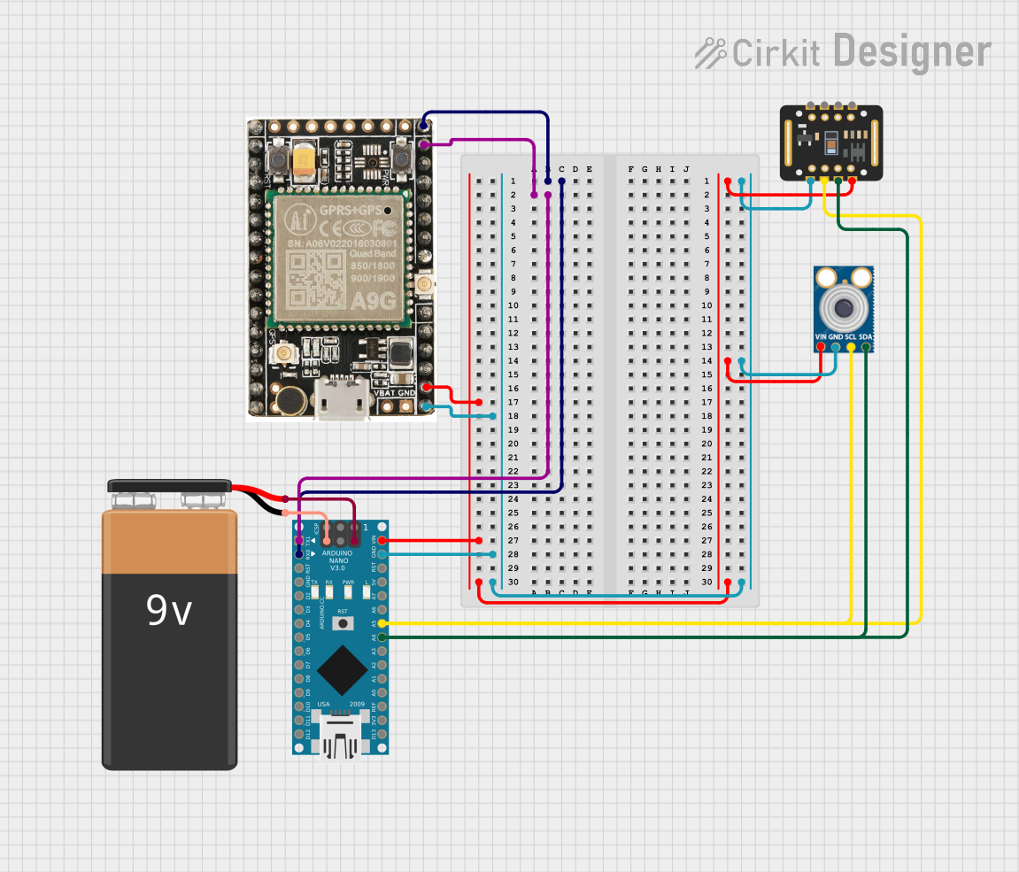

Explore Projects Built with A9G