How to Use 1602 LCD Keypad Shield: Examples, Pinouts, and Specs
1602 LCD Keypad Shield Documentation
Manufacturer: DF Robot Drive the Future
Part ID: DF
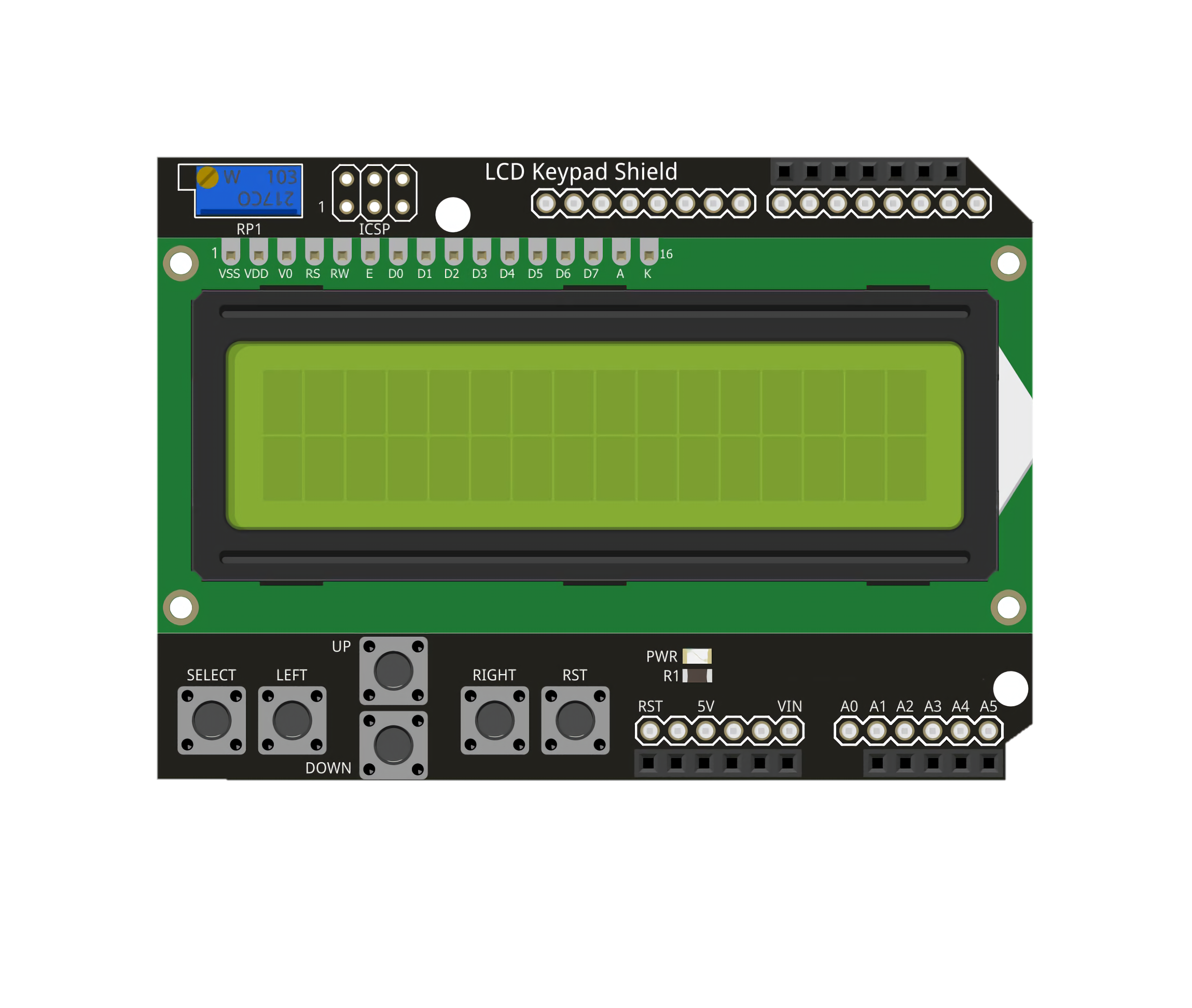
Description: The 1602 LCD Keypad Shield is an add-on board designed for microcontrollers, particularly Arduino boards. It features a 16x2 character LCD display and a 4x4 keypad for user input. This shield simplifies the process of adding a display and input interface to your projects, making it ideal for interactive applications such as menu navigation, data display, and user-controlled systems.
1. Introduction
The 1602 LCD Keypad Shield is a versatile and user-friendly component that combines a 16x2 LCD display with a 4x4 keypad. The LCD can display two lines of 16 characters each, while the keypad provides five buttons (SELECT, LEFT, RIGHT, UP, DOWN) for user interaction. This shield is designed to stack directly onto an Arduino board, making it easy to integrate into your projects without additional wiring.
Common Applications:
- Menu-based interfaces: Create interactive menus for user input and navigation.
- Data monitoring: Display sensor readings, system status, or other real-time data.
- Timers and counters: Build countdown timers or event counters with user control.
- Educational projects: Ideal for learning about microcontroller programming and interfacing.
2. Technical Specifications
Key Technical Details
| Parameter | Specification |
|---|---|
| LCD Type | 16x2 character LCD |
| Backlight | Blue backlight with white text |
| Keypad Buttons | 5 buttons (SELECT, LEFT, RIGHT, UP, DOWN) |
| Operating Voltage | 5V DC |
| Current Consumption | ~20mA (with backlight on) |
| Interface | Parallel (uses Arduino digital pins) |
| Dimensions | 80mm x 58mm x 20mm |
Pin Configuration and Descriptions
The 1602 LCD Keypad Shield uses the following Arduino pins for operation:
| Pin | Function | Description |
|---|---|---|
| D4 | LCD Data Line (D4) | Transfers data to the LCD. |
| D5 | LCD Data Line (D5) | Transfers data to the LCD. |
| D6 | LCD Data Line (D6) | Transfers data to the LCD. |
| D7 | LCD Data Line (D7) | Transfers data to the LCD. |
| D8 | LCD RS (Register Select) | Selects command or data register. |
| D9 | LCD Enable (E) | Enables the LCD for data transfer. |
| A0 | Keypad Input | Reads the analog voltage from the keypad buttons. |
3. Usage Instructions
Connecting the Shield to an Arduino
- Align the pins of the 1602 LCD Keypad Shield with the headers on your Arduino board.
- Carefully press the shield onto the Arduino, ensuring all pins are securely connected.
- Power the Arduino via USB or an external power source.
Writing Code for the Shield
To use the shield, you will need the LiquidCrystal library, which is included with the Arduino IDE. Below is an example code snippet to display text on the LCD and read button presses.
#include <LiquidCrystal.h>

// Initialize the LCD with the pins used by the shield
LiquidCrystal lcd(8, 9, 4, 5, 6, 7);

// Define button thresholds for the analog input (A0)
#define BTN_RIGHT  0
#define BTN_UP     100
#define BTN_DOWN   200
#define BTN_LEFT   300
#define BTN_SELECT 400
#define BTN_NONE   1000

int readButton() {
  int adcValue = analogRead(A0); // Read the analog value from A0

  // Map the ADC value to a button
  if (adcValue < 50) return BTN_RIGHT;
  if (adcValue < 150) return BTN_UP;
  if (adcValue < 250) return BTN_DOWN;
  if (adcValue < 350) return BTN_LEFT;
  if (adcValue < 450) return BTN_SELECT;
  return BTN_NONE; // No button pressed
}

void setup() {
  lcd.begin(16, 2); // Initialize the LCD with 16 columns and 2 rows
  lcd.print("Hello, World!"); // Display a welcome message
}

void loop() {
  int button = readButton(); // Read the button press

  lcd.setCursor(0, 1); // Move to the second line
  switch (button) {
    case BTN_RIGHT:
      lcd.print("Right  "); // Display "Right" if the RIGHT button is pressed
      break;
    case BTN_UP:
      lcd.print("Up     "); // Display "Up" if the UP button is pressed
      break;
    case BTN_DOWN:
      lcd.print("Down   "); // Display "Down" if the DOWN button is pressed
      break;
    case BTN_LEFT:
      lcd.print("Left   "); // Display "Left" if the LEFT button is pressed
      break;
    case BTN_SELECT:
      lcd.print("Select "); // Display "Select" if the SELECT button is pressed
      break;
    default:
      lcd.print("No Btn "); // Display "No Btn" if no button is pressed
      break;
  }
  delay(200); // Add a small delay to debounce the buttons
}
Important Considerations
- Power Supply: Ensure your Arduino is powered adequately, especially if other components are connected.
- Button Debouncing: The buttons may require software debouncing for reliable operation.
- Backlight Control: The backlight is always on by default. To save power, you can modify the shield to control the backlight via a digital pin.
4. Troubleshooting and FAQs
Common Issues and Solutions
| Issue | Possible Cause | Solution |
|---|---|---|
| LCD does not display text | Incorrect pin connections | Ensure the shield is properly seated on the Arduino. |
| Buttons do not respond | Faulty analog input or loose connection | Check the A0 pin and ensure the shield is secure. |
| Text is garbled or unclear | Incorrect initialization in code | Verify the lcd.begin() parameters in your code. |
| Backlight is not working | Hardware issue or modification error | Check the backlight circuit or connections. |
Frequently Asked Questions
Q: Can I use this shield with other microcontrollers?
A: The shield is designed for Arduino boards, but it can be used with other microcontrollers that support 5V logic and have compatible pinouts.
Q: How do I adjust the contrast of the LCD?
A: The shield includes a small potentiometer to adjust the contrast. Turn it gently with a screwdriver to achieve the desired contrast.
Q: Can I use the keypad and LCD simultaneously?
A: Yes, the keypad and LCD operate independently. The LCD uses digital pins, while the keypad uses the analog pin (A0).
This documentation provides a comprehensive guide to using the 1602 LCD Keypad Shield. Whether you're a beginner or an experienced user, this shield is a powerful tool for creating interactive projects with ease.
Explore Projects Built with 1602 LCD Keypad Shield
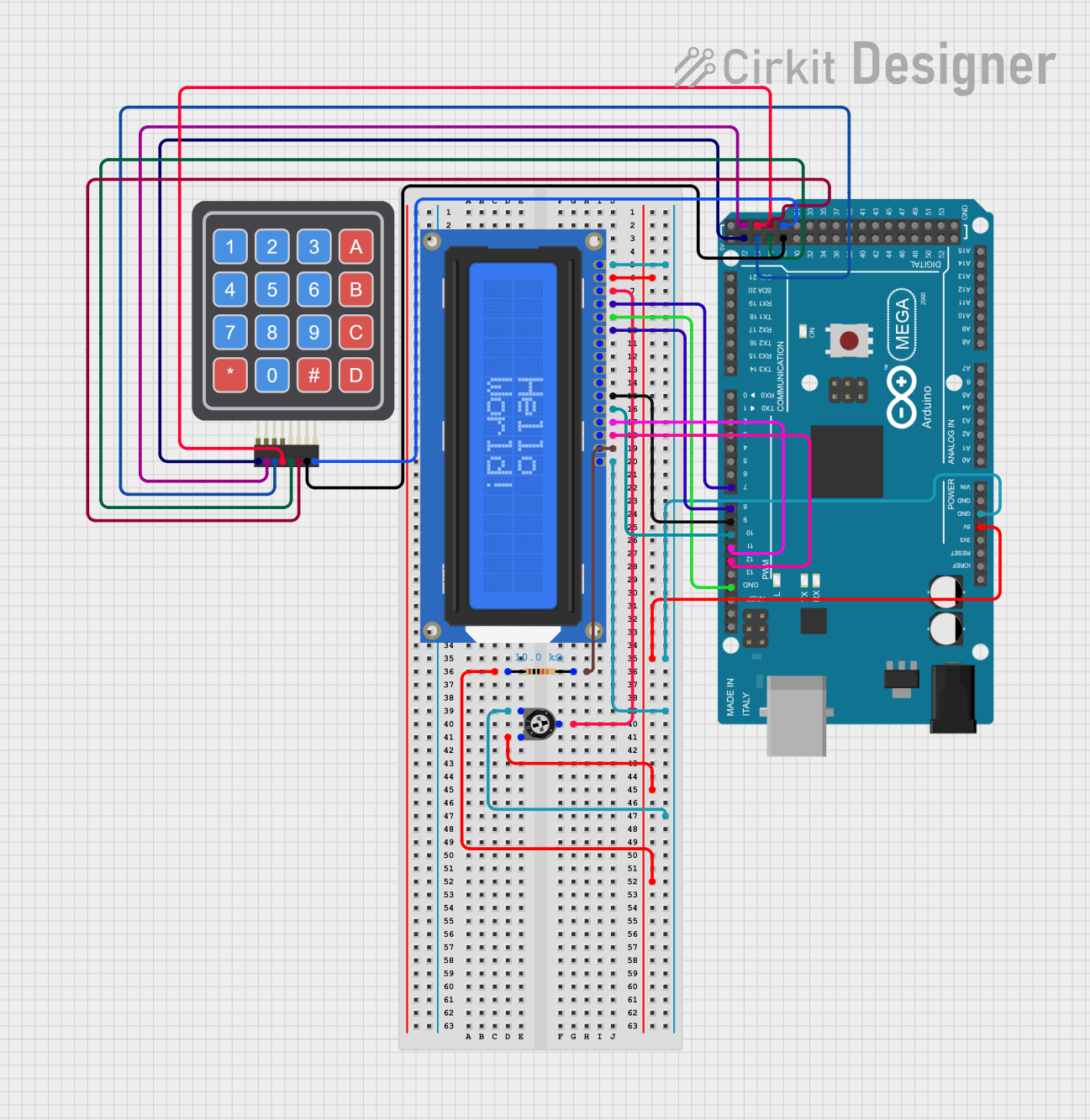
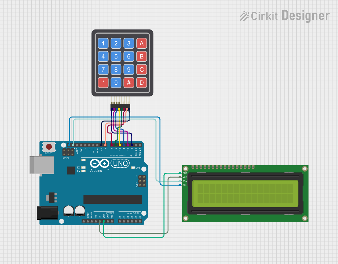
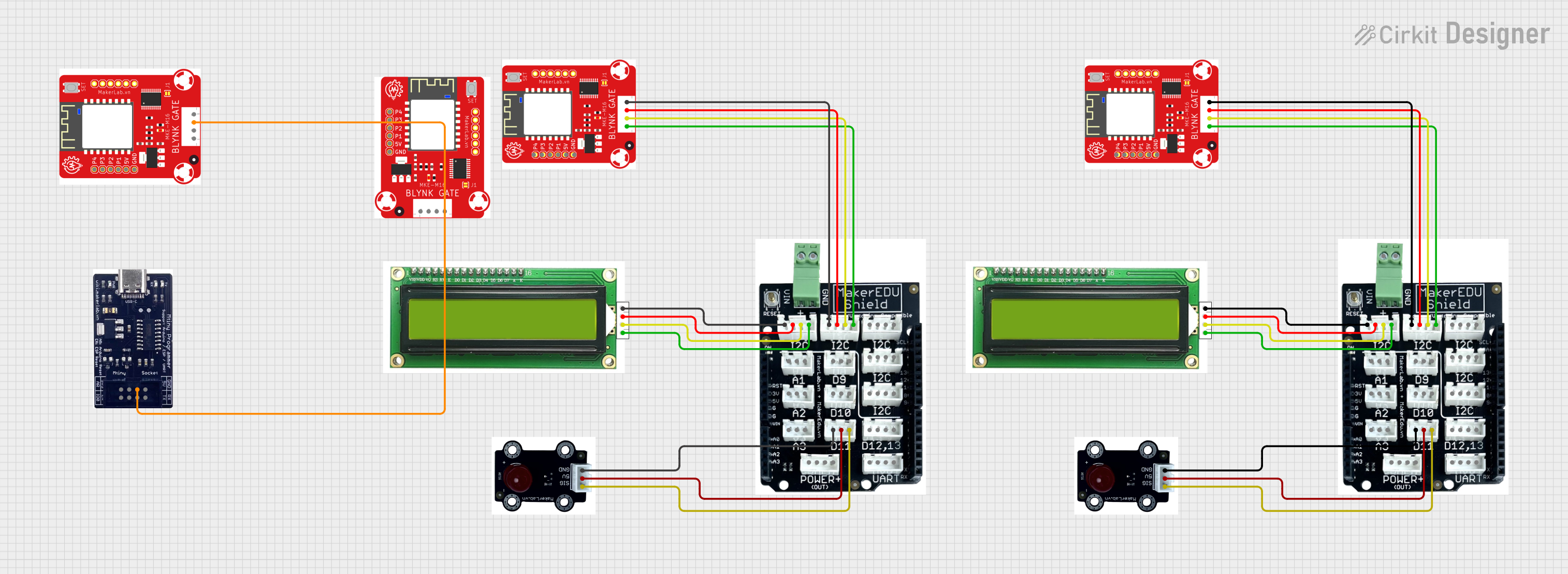
Explore Projects Built with 1602 LCD Keypad Shield