Cirkit Designer Logo
Cirkit Designer
Your all-in-one circuit design IDE
Home / 
Component Documentation

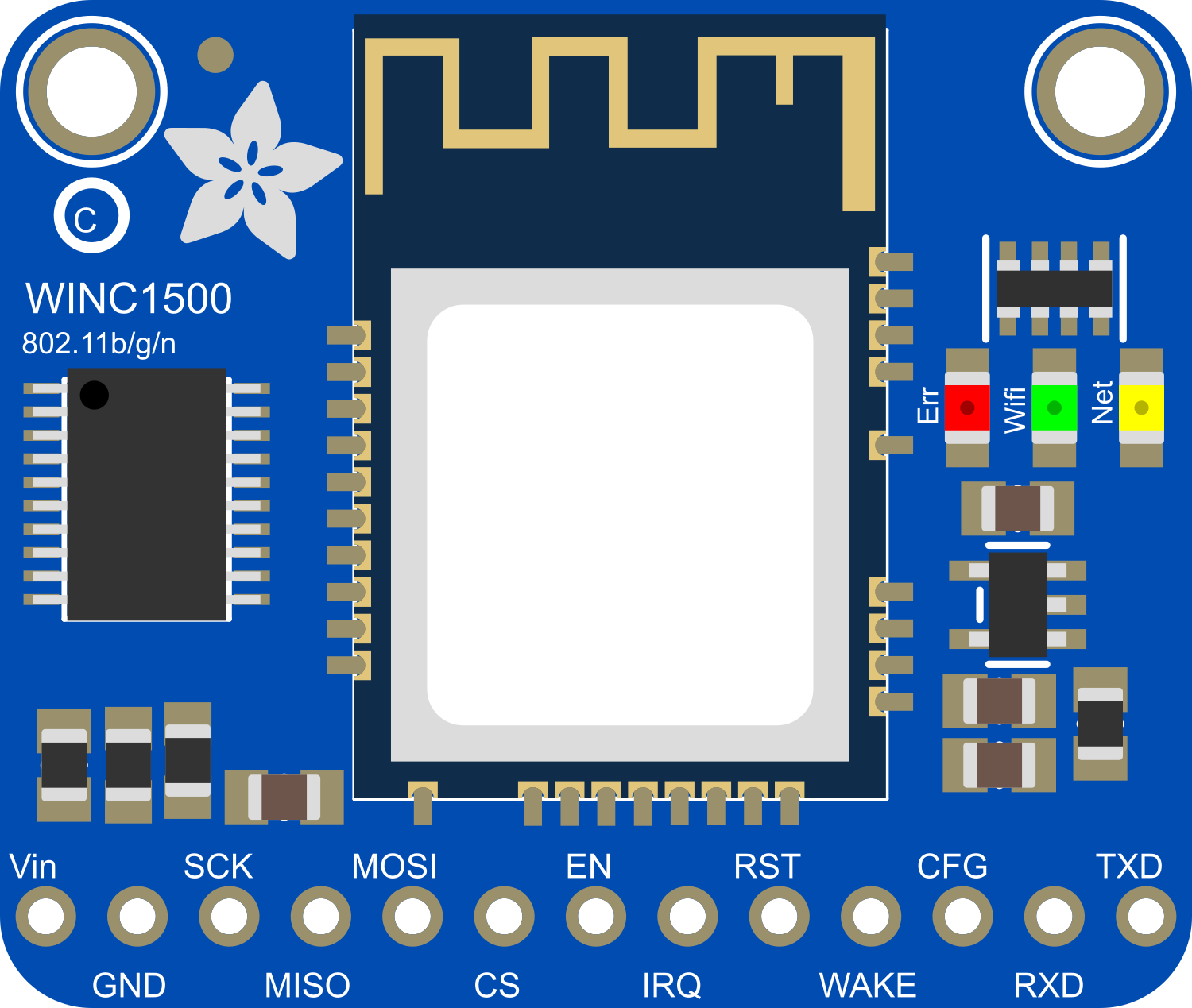
How to Use Adafruit WINC1500 PCB Antenna Breakout: Examples, Pinouts, and Specs

Image of Adafruit WINC1500 PCB Antenna Breakout
Cirkit Designer LogoDesign with Adafruit WINC1500 PCB Antenna Breakout in Cirkit Designer

Introduction

The Adafruit WINC1500 PCB Antenna Breakout is a compact wireless network module that enables microcontrollers and microcomputers to connect to 802.11 b/g/n Wi-Fi networks. This breakout board integrates the Microchip WINC1500 Wi-Fi module, which is specifically designed for low-power Internet of Things (IoT) applications. The onboard PCB antenna makes this module a convenient choice for wireless data communication.

Explore Projects Built with Adafruit WINC1500 PCB Antenna Breakout

Use Cirkit Designer to design, explore, and prototype these projects online. Some projects support real-time simulation. Click "Open Project" to start designing instantly!
Arduino Pro Mini FM Radio with LCD Display and Battery Power
Image of DIY FM Radio RDA5807M V2: A project utilizing Adafruit WINC1500 PCB Antenna Breakout in a practical application
This circuit is a portable FM radio receiver with an integrated display and audio output. It uses an Arduino Pro Mini to control an RDA5807M FM receiver module, an ADS1115 ADC for additional analog inputs, and a PAM8403 amplifier to drive loudspeakers. The circuit also includes a rotary encoder for user input, an LCD screen for displaying information, and a boost converter for power management.
Cirkit Designer LogoOpen Project in Cirkit Designer
Arduino UNO R4 WiFi Environmental Data Logger with I2C Multiplexing and SD Storage
Image of scannerII: A project utilizing Adafruit WINC1500 PCB Antenna Breakout in a practical application
This circuit features an Arduino UNO R4 WiFi as the central microcontroller, interfaced with a BME280 Breakout sensor for environmental data, an SD card module for data logging, and a TCA9548A I2C multiplexer to manage multiple I2C devices. It also includes a U078-V-M12 sensor and an SPS30 particulate matter sensor, both connected through the I2C multiplexer. Power distribution is managed by a dedicated board that receives 3.3V from the Arduino and distributes it to the SD card module and other components.
Cirkit Designer LogoOpen Project in Cirkit Designer
Arduino UNO WiFi with Heart Pulse and Temperature Monitoring
Image of BioTrackers: A project utilizing Adafruit WINC1500 PCB Antenna Breakout in a practical application
This circuit features an Arduino UNO R4 WiFi microcontroller connected to a Heart Pulse Sensor and an SHT1x-Breakout sensor. The Arduino is configured to read heart pulse signals from the Heart Pulse Sensor on analog pin A0 and temperature/humidity data from the SHT1x-Breakout sensor via the I2C interface on pins A4 (DATA) and A5 (SCK). Both sensors are powered by the Arduino's 5V output, and their ground pins are connected to the Arduino's ground.
Cirkit Designer LogoOpen Project in Cirkit Designer
Arduino UNO WiFi Sensor Data Acquisition and Display System
Image of Senior Design: A project utilizing Adafruit WINC1500 PCB Antenna Breakout in a practical application
This circuit features an Arduino UNO R4 WiFi microcontroller interfacing with a 4-channel ADC to read from various sensors and display data on an I2C LCD screen. A pushbutton provides user input, and a DC-DC buck converter regulates the power supply from a 12V source.
Cirkit Designer LogoOpen Project in Cirkit Designer

Explore Projects Built with Adafruit WINC1500 PCB Antenna Breakout

Use Cirkit Designer to design, explore, and prototype these projects online. Some projects support real-time simulation. Click "Open Project" to start designing instantly!
Image of DIY FM Radio RDA5807M V2: A project utilizing Adafruit WINC1500 PCB Antenna Breakout in a practical application
Arduino Pro Mini FM Radio with LCD Display and Battery Power
This circuit is a portable FM radio receiver with an integrated display and audio output. It uses an Arduino Pro Mini to control an RDA5807M FM receiver module, an ADS1115 ADC for additional analog inputs, and a PAM8403 amplifier to drive loudspeakers. The circuit also includes a rotary encoder for user input, an LCD screen for displaying information, and a boost converter for power management.
Cirkit Designer LogoOpen Project in Cirkit Designer
Image of scannerII: A project utilizing Adafruit WINC1500 PCB Antenna Breakout in a practical application
Arduino UNO R4 WiFi Environmental Data Logger with I2C Multiplexing and SD Storage
This circuit features an Arduino UNO R4 WiFi as the central microcontroller, interfaced with a BME280 Breakout sensor for environmental data, an SD card module for data logging, and a TCA9548A I2C multiplexer to manage multiple I2C devices. It also includes a U078-V-M12 sensor and an SPS30 particulate matter sensor, both connected through the I2C multiplexer. Power distribution is managed by a dedicated board that receives 3.3V from the Arduino and distributes it to the SD card module and other components.
Cirkit Designer LogoOpen Project in Cirkit Designer
Image of BioTrackers: A project utilizing Adafruit WINC1500 PCB Antenna Breakout in a practical application
Arduino UNO WiFi with Heart Pulse and Temperature Monitoring
This circuit features an Arduino UNO R4 WiFi microcontroller connected to a Heart Pulse Sensor and an SHT1x-Breakout sensor. The Arduino is configured to read heart pulse signals from the Heart Pulse Sensor on analog pin A0 and temperature/humidity data from the SHT1x-Breakout sensor via the I2C interface on pins A4 (DATA) and A5 (SCK). Both sensors are powered by the Arduino's 5V output, and their ground pins are connected to the Arduino's ground.
Cirkit Designer LogoOpen Project in Cirkit Designer
Image of Senior Design: A project utilizing Adafruit WINC1500 PCB Antenna Breakout in a practical application
Arduino UNO WiFi Sensor Data Acquisition and Display System
This circuit features an Arduino UNO R4 WiFi microcontroller interfacing with a 4-channel ADC to read from various sensors and display data on an I2C LCD screen. A pushbutton provides user input, and a DC-DC buck converter regulates the power supply from a 12V source.
Cirkit Designer LogoOpen Project in Cirkit Designer

Common Applications and Use Cases

  • IoT devices
  • Remote sensor networks
  • Wireless data loggers
  • Home automation systems
  • Robotics

Technical Specifications

Key Technical Details

  • Wi-Fi Standards: 802.11 b/g/n
  • Frequency Range: 2.4 GHz ISM Band
  • Security Protocols: WEP, WPA/WPA2 PSK/Enterprise
  • Integrated TCP/IP stack
  • Power Supply: 3.3V
  • Interface: SPI
  • Operating Temperature: -40°C to +85°C

Pin Configuration and Descriptions

Pin Number Name Description
1 GND Ground
2 3V3 3.3V Supply
3 EN Enable Pin
4 RST Reset Pin
5 SCK SPI Clock
6 MISO SPI MISO
7 MOSI SPI MOSI
8 CS SPI Chip Select
9 IRQ Interrupt Request
10 WAKE Wake-up Pin

Usage Instructions

How to Use the Component in a Circuit

  1. Power Supply: Connect the 3V3 pin to a 3.3V power source and the GND pin to the ground.
  2. SPI Interface: Connect the SCK, MISO, MOSI, and CS pins to the corresponding SPI interface pins on your microcontroller.
  3. Control Pins: Connect the EN and RST pins to digital I/O pins on your microcontroller for enabling and resetting the module.
  4. Interrupts: Optionally, connect the IRQ pin to an interrupt-capable pin on your microcontroller to handle asynchronous events.
  5. Wake-up: The WAKE pin can be used to wake the module from sleep mode.

Important Considerations and Best Practices

  • Ensure that the power supply is stable and clean to prevent any damage to the module.
  • Use proper decoupling capacitors close to the module's power supply pins to minimize power supply noise.
  • Keep the SPI lines as short as possible to reduce signal degradation.
  • Follow proper ESD precautions when handling the breakout board to avoid damaging the sensitive Wi-Fi module.

Example Code for Arduino UNO

#include <SPI.h>
#include <WiFi101.h>

// Your network SSID and password
char ssid[] = "your_network_SSID";
char pass[] = "your_password";

void setup() {
  Serial.begin(9600);

  // Check for the presence of the shield
  if (WiFi.status() == WL_NO_SHIELD) {
    Serial.println("WiFi shield not present");
    // Don't continue
    while (true);
  }

  // Attempt to connect to WiFi network
  while (WiFi.begin(ssid, pass) != WL_CONNECTED) {
    Serial.print("Attempting to connect to SSID: ");
    Serial.println(ssid);
    // Wait 10 seconds before retrying
    delay(10000);
  }

  Serial.println("Connected to wifi");
  printWiFiStatus();
}

void loop() {
  // Add your regular code here
}

void printWiFiStatus() {
  // Print the SSID of the network you're attached to
  Serial.print("SSID: ");
  Serial.println(WiFi.SSID());

  // Print your board's IP address
  IPAddress ip = WiFi.localIP();
  Serial.print("IP Address: ");
  Serial.println(ip);

  // Print the received signal strength
  long rssi = WiFi.RSSI();
  Serial.print("Signal strength (RSSI):");
  Serial.print(rssi);
  Serial.println(" dBm");
}

Troubleshooting and FAQs

Common Issues

  • Module not responding: Ensure that the module is correctly powered and that the SPI connections are secure.
  • Unable to connect to Wi-Fi: Verify that the SSID and password are correct and that the Wi-Fi network is within range.
  • Intermittent connectivity: Check for sources of Wi-Fi interference or signal obstructions.

Solutions and Tips for Troubleshooting

  • Reset the module using the RST pin if it becomes unresponsive.
  • Use serial output to debug and verify that the module is initializing correctly.
  • Ensure that the antenna area is not obstructed by metal objects or electronic components that could interfere with the signal.

FAQs

Q: Can the WINC1500 be used with a 5V microcontroller? A: Yes, but level shifters should be used on the SPI lines to protect the 3.3V logic of the WINC1500.

Q: Does the WINC1500 support over-the-air (OTA) updates? A: Yes, the WINC1500 supports OTA updates, which can be implemented through the provided library functions.

Q: How can I improve the range of the Wi-Fi connection? A: Ensure that the PCB antenna is not obstructed and consider the orientation of the breakout board for optimal signal reception. Additionally, external antennas can be used if the breakout board version supports it.