How to Use T-Display-S3 AMOLED: Examples, Pinouts, and Specs
Introduction
The T-Display-S3 AMOLED by LilyGo is a compact and vibrant display module designed for use in a wide range of electronics projects. Featuring an Active Matrix Organic Light Emitting Diode (AMOLED) screen, it provides excellent color reproduction, deep blacks, and high contrast ratios. This display is particularly well-suited for portable devices, wearables, and any application where a high-quality visual output is desired.
Explore Projects Built with T-Display-S3 AMOLED


Explore Projects Built with T-Display-S3 AMOLED
Common Applications and Use Cases
- Wearable devices
- Portable instrumentation
- User interfaces for IoT devices
- DIY electronics projects
- Educational tools and demonstrations
Technical Specifications
Key Technical Details
- Display Type: AMOLED
- Screen Size: 1.9 inches
- Resolution: 320x390 pixels
- Color Depth: 16-bit
- Interface: SPI
- Operating Voltage: 3.3V
- Logic Level: 3.3V
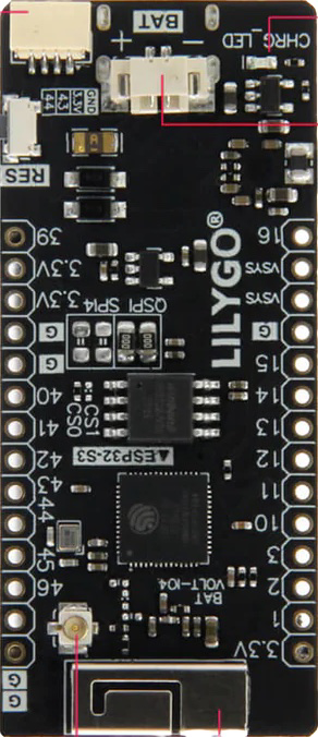
Pin Configuration and Descriptions
| Pin Number | Pin Name | Description |
|---|---|---|
| 1 | GND | Ground |
| 2 | VCC | Power supply (3.3V) |
| 3 | SCL | SPI clock line |
| 4 | SDA | SPI data line |
| 5 | RES | Reset line for the display controller |
| 6 | DC | Data/Command control pin |
| 7 | BLK | Backlight control pin |
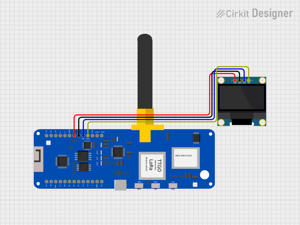
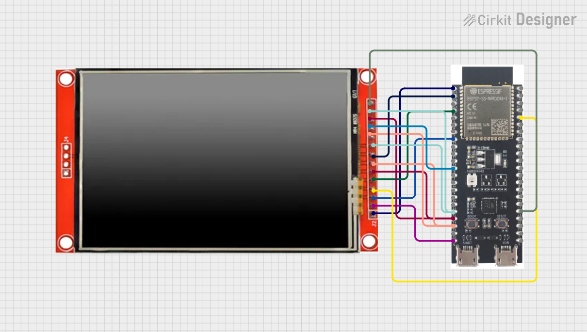
Usage Instructions
How to Use the Component in a Circuit
- Power Connections: Connect the VCC pin to a 3.3V power source and the GND pin to the ground.
- SPI Interface: Connect the SCL and SDA pins to the corresponding SPI clock and data lines on your microcontroller.
- Control Pins: Connect the RES pin to a digital output for resetting the display. The DC pin should also be connected to a digital output for sending commands or data. The BLK pin can be connected to a PWM output for backlight control.
- Mounting: Secure the display module to your project using the mounting holes provided.
Important Considerations and Best Practices
- Ensure that the power supply is stable and does not exceed 3.3V.
- Use a level shifter if interfacing with a 5V microcontroller to avoid damaging the display.
- Avoid exposing the display to direct sunlight for extended periods to prevent damage.
- Handle the display with care to avoid physical damage to the screen.
Example Code for Arduino UNO
#include <SPI.h>
#include <Adafruit_GFX.h>
#include <Adafruit_SSD1306.h>

#define SCREEN_WIDTH 128 // OLED display width, in pixels
#define SCREEN_HEIGHT 64 // OLED display height, in pixels

// Declaration for an SSD1306 display connected to SPI
#define OLED_RESET     4 // Reset pin # (or -1 if sharing Arduino reset pin)
Adafruit_SSD1306 display(SCREEN_WIDTH, SCREEN_HEIGHT, &SPI, OLED_DC, OLED_RESET, OLED_CS);

void setup() {
  // Initialize with the I2C addr 0x3D (for the 128x64)
  if(!display.begin(SSD1306_SWITCHCAPVCC, 0x3D)) {
    Serial.println(F("SSD1306 allocation failed"));
    for(;;);
  }
  display.display();
  delay(2000); // Pause for 2 seconds

  // Clear the buffer
  display.clearDisplay();

  // Draw a single pixel in white
  display.drawPixel(10, 10, SSD1306_WHITE);

  // Show the display buffer on the screen
  display.display();
  delay(2000); // Pause for 2 seconds
}

void loop() {
  // Put your main code here, to run repeatedly:
}
Note: The above code is for illustration purposes only and may require modifications to work with the T-Display-S3 AMOLED. Please refer to the specific library and pin definitions for the T-Display-S3 AMOLED.
Troubleshooting and FAQs
Common Issues
- Display not powering on: Check the power connections and ensure the voltage is 3.3V.
- No image on the display: Verify that the SPI connections are correct and that the correct pins are being used for DC and RES.
- Dim or flickering display: Ensure that the BLK pin is connected properly and that the PWM signal is stable.
Solutions and Tips for Troubleshooting
- Double-check all connections and ensure that solder joints are solid and not causing intermittent connections.
- Use example code and libraries specifically designed for the T-Display-S3 AMOLED to ensure compatibility.
- If the display is still not working, try using another known-good display to determine if the issue is with the display module or the microcontroller setup.
FAQs
Q: Can I use the T-Display-S3 AMOLED with a 5V microcontroller? A: Yes, but you must use a level shifter to convert the 5V signals to 3.3V to avoid damaging the display.
Q: Is it possible to control the brightness of the display? A: Yes, the brightness can be controlled via the BLK pin using PWM.
Q: What library should I use for the T-Display-S3 AMOLED? A: Libraries that support SPI AMOLED displays, such as Adafruit's SSD1306 library, can be used. However, you may need to make adjustments for compatibility with the T-Display-S3 AMOLED's specific resolution and controller.
Q: How do I update the display content?
A: After drawing your content to the display buffer using the library's graphics functions, call the display() function to update the screen.
Q: Can I use this display for full-motion video? A: While the AMOLED display is capable of high refresh rates, the SPI interface may limit the frame rate achievable. It is suitable for simple animations and user interfaces but may not be ideal for full-motion video.