How to Use DPDT 5v Relay: Examples, Pinouts, and Specs
Introduction
The Double Pole Double Throw (DPDT) 5V relay is an electromechanical switch that allows you to control two independent circuits simultaneously. Operating at a 5V DC input, this relay can switch between two states, enabling both on/off control and direction switching. It is widely used in applications requiring electrical isolation, such as motor control, home automation, and industrial systems.
Explore Projects Built with DPDT 5v Relay


Explore Projects Built with DPDT 5v Relay
Common Applications:
- Motor direction control (e.g., forward/reverse)
- Switching between two power sources
- Home automation systems
- Signal routing in audio or communication systems
- Industrial control systems
Technical Specifications
Below are the key technical details of the DPDT 5V relay:
| Parameter | Value |
|---|---|
| Operating Voltage | 5V DC |
| Coil Resistance | ~70 Ω |
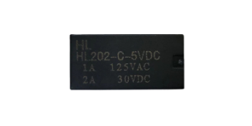
| Switching Voltage | Up to 250V AC / 30V DC |
| Switching Current | Up to 10A |
| Contact Configuration | Double Pole Double Throw (DPDT) |
| Isolation | Electrical isolation between control and load |
| Dimensions | Varies by manufacturer (e.g., ~28mm x 10mm x 15mm) |
| Operating Temperature | -40°C to 85°C |
Pin Configuration
The DPDT relay typically has 8 pins. Below is the pinout description:
| Pin Number | Name | Description |
|---|---|---|
| 1 | Coil (+) | Positive terminal of the relay coil (connect to 5V DC) |
| 2 | Coil (-) | Negative terminal of the relay coil (connect to ground) |
| 3 | Common 1 (COM1) | Common terminal for the first pole of the relay |
| 4 | Normally Closed 1 (NC1) | Connected to COM1 when the relay is inactive (coil not energized) |
| 5 | Normally Open 1 (NO1) | Connected to COM1 when the relay is active (coil energized) |
| 6 | Common 2 (COM2) | Common terminal for the second pole of the relay |
| 7 | Normally Closed 2 (NC2) | Connected to COM2 when the relay is inactive (coil not energized) |
| 8 | Normally Open 2 (NO2) | Connected to COM2 when the relay is active (coil energized) |
Usage Instructions
How to Use the DPDT 5V Relay in a Circuit
- Power the Relay Coil: Connect the coil pins (1 and 2) to a 5V DC power source. Use a transistor or relay driver circuit to control the coil, as the relay may require more current than a microcontroller pin can supply.
- Connect the Load:
- For the first circuit, connect the load to COM1 (pin 3) and either NC1 (pin 4) or NO1 (pin 5), depending on the desired default state.
- For the second circuit, connect the load to COM2 (pin 6) and either NC2 (pin 7) or NO2 (pin 8).
- Control the Relay: Use a microcontroller, switch, or other control signal to energize the relay coil. When the coil is energized, the relay switches from NC to NO for both poles.
Important Considerations:
- Back-EMF Protection: Always use a flyback diode across the coil terminals to protect your circuit from voltage spikes when the relay is de-energized.
- Current Ratings: Ensure the load current does not exceed the relay's maximum switching current (10A).
- Isolation: The relay provides electrical isolation between the control circuit and the load, making it safe for high-voltage applications.
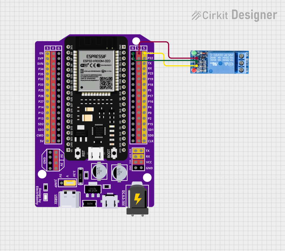
Example: Controlling a DPDT 5V Relay with Arduino UNO
Below is an example of how to control a DPDT 5V relay using an Arduino UNO:
// Define the pin connected to the relay control circuit
const int relayPin = 7; // Connect this pin to the base of a transistor or relay module

void setup() {
  pinMode(relayPin, OUTPUT); // Set the relay pin as an output
  digitalWrite(relayPin, LOW); // Ensure the relay is off initially
}

void loop() {
  // Turn the relay on
  digitalWrite(relayPin, HIGH);
  delay(5000); // Keep the relay on for 5 seconds

  // Turn the relay off
  digitalWrite(relayPin, LOW);
  delay(5000); // Keep the relay off for 5 seconds
}
Note: Use a transistor (e.g., 2N2222) or a relay driver module to interface the Arduino with the relay, as the Arduino pin cannot directly supply the required current.
Troubleshooting and FAQs
Common Issues and Solutions
Relay Not Switching:
- Cause: Insufficient current to the coil.
- Solution: Use a transistor or relay driver circuit to provide adequate current.
Chattering or Unstable Operation:
- Cause: Noise or insufficient power supply.
- Solution: Add a capacitor (e.g., 100µF) across the power supply to stabilize it.
Load Not Switching:
- Cause: Incorrect wiring of the load to the relay terminals.
- Solution: Double-check the connections to COM, NC, and NO pins.
Burnt Relay Contacts:
- Cause: Exceeding the relay's current or voltage ratings.
- Solution: Ensure the load does not exceed the relay's maximum ratings.
FAQs
Q1: Can I use the DPDT 5V relay with an AC load?
A1: Yes, the relay can switch AC loads up to its rated voltage and current. Ensure proper isolation and safety precautions.
Q2: Why do I need a flyback diode?
A2: The flyback diode protects your circuit from voltage spikes generated when the relay coil is de-energized.
Q3: Can I control the relay directly with a microcontroller?
A3: No, most microcontroller pins cannot supply enough current to energize the relay coil. Use a transistor or relay driver module.
Q4: What is the difference between NC and NO terminals?
A4: NC (Normally Closed) is connected to the common terminal when the relay is inactive, while NO (Normally Open) is connected when the relay is active.