How to Use INA219: Examples, Pinouts, and Specs
Introduction
The INA219 is a high-side current shunt and power monitor with an I2C-compatible interface. The device monitors both shunt voltage drop and bus supply voltage, with programmable conversion times and filtering. A precision current-sensing amplifier, an analog-to-digital converter (ADC), and a data acquisition system are integrated into the INA219. It is commonly used in applications such as power management, system protection, battery chargers, and automotive systems.
Explore Projects Built with INA219
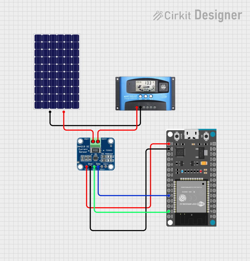
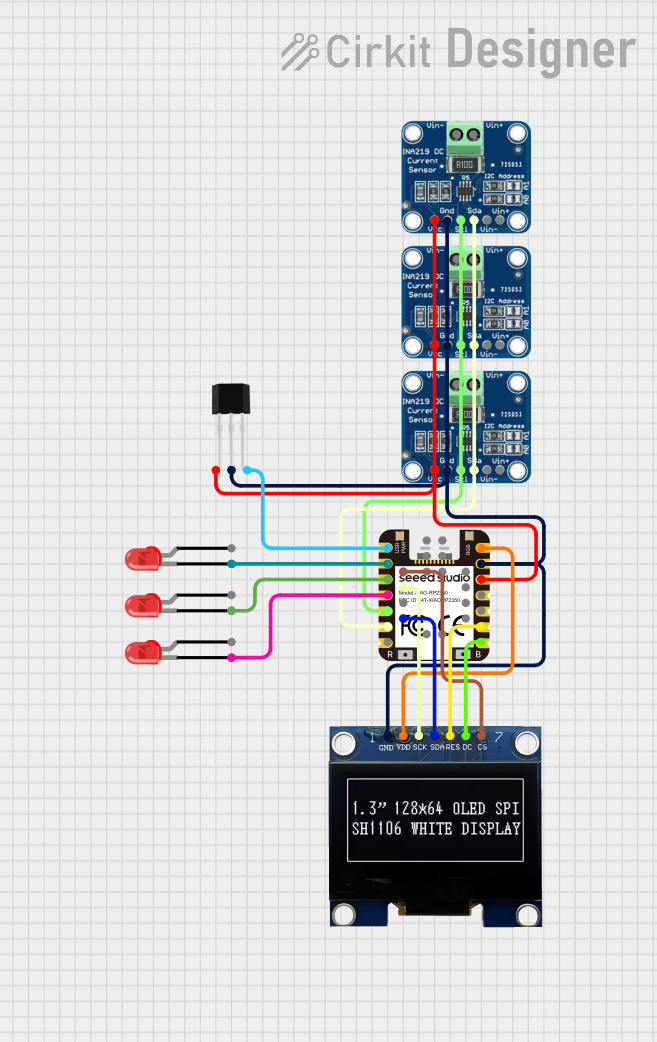
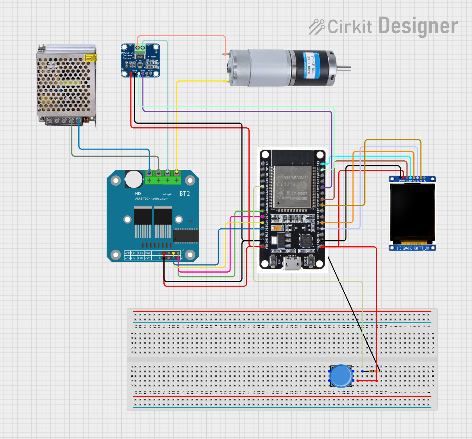
Explore Projects Built with INA219
Common Applications and Use Cases
- Battery monitoring
- Energy management
- Power supply monitoring
- Overcurrent protection systems
- Solar power monitoring
Technical Specifications
Key Technical Details
- Voltage Range (Bus): 0 to 26V
- Current Range: -3.2A to +3.2A (with a 0.1 ohm shunt)
- Resolution: 0.8mA with a 0.1 ohm shunt
- I2C Interface: Supports standard (100kHz), fast (400kHz), and high-speed (3.4MHz) modes
- Operating Voltage: 3.0V to 5.5V
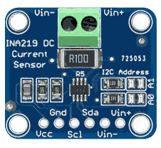
Pin Configuration and Descriptions
| Pin Number | Name | Description |
|---|---|---|
| 1 | V_IN+ | Positive voltage input. Connect to the positive side of the power supply. |
| 2 | V_IN- | Negative voltage input. Connect to the load side of the shunt resistor. |
| 3 | GND | Ground. Connect to the system ground. |
| 4 | SDA | I2C Data. Connect to the I2C data line. |
| 5 | SCL | I2C Clock. Connect to the I2C clock line. |
| 6 | A0 | Address pin. Connect to GND or Vcc to set the I2C address. |
| 7 | A1 | Address pin. Connect to GND or Vcc to set the I2C address. |
| 8 | Vcc | Power supply for the INA219. Connect to 3.0V to 5.5V. |
Usage Instructions
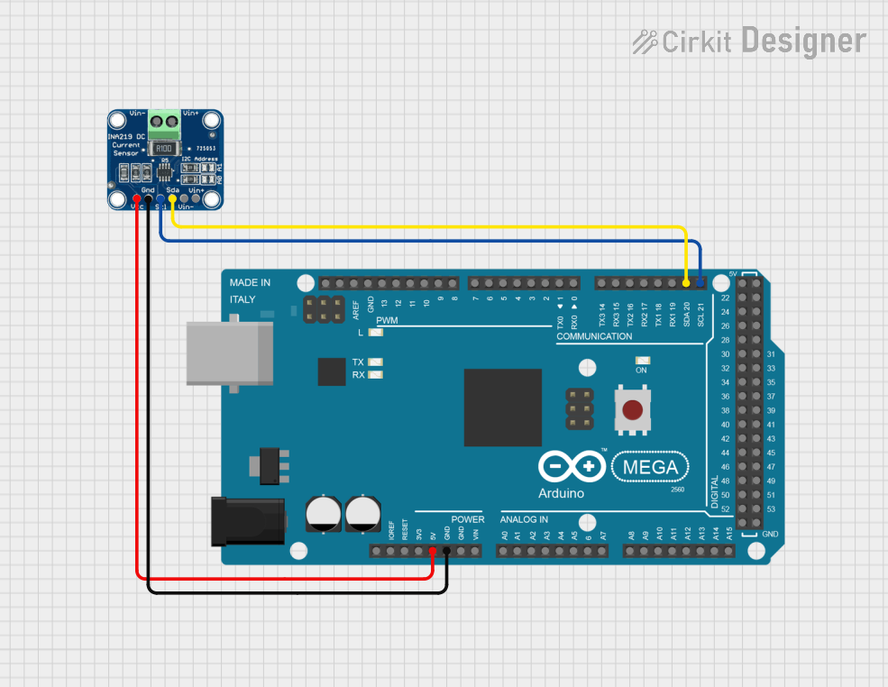
How to Use the INA219 in a Circuit
- Connect the Power Supply: Connect Vcc to a 3.0V to 5.5V power supply and GND to the system ground.
- Shunt Resistor: Connect a shunt resistor between the source of the power and V_IN+ pin, and connect the load to the V_IN- pin.
- I2C Interface: Connect SDA and SCL to the I2C data and clock lines on your microcontroller.
- Address Pins: Set the A0 and A1 pins to either GND or Vcc to configure the I2C address of the INA219.
Important Considerations and Best Practices
- Ensure that the power supply voltage does not exceed the maximum rating of 5.5V.
- The shunt resistor value determines the maximum current measurement range.
- Use pull-up resistors on the SDA and SCL lines if they are not already present on the microcontroller board.
- Avoid placing the INA219 near high-heat sources to prevent thermal drift in measurements.
Example Code for Arduino UNO
#include <Wire.h>
#include <Adafruit_INA219.h>

Adafruit_INA219 ina219;

void setup(void)
{
  Serial.begin(9600);
  while (!Serial) {
      // Wait for Serial to be ready
  }

  uint32_t currentFrequency;

  // Initialize the INA219.
  // By default the initialization will use the largest range (32V, 2A).
  if (!ina219.begin()) {
    Serial.println("Failed to find INA219 chip");
    while (1) { delay(10); }
  }
  // To use a slightly lower 32V, 1A range (higher precision on amps):
  // ina219.setCalibration_32V_1A();
  // Or to use a lower 16V, 400mA range (higher precision on volts and amps):
  // ina219.setCalibration_16V_400mA();

  Serial.println("Measuring voltage and current with INA219 ...");
}

void loop(void)
{
  float shuntvoltage = 0;
  float busvoltage = 0;
  float current_mA = 0;
  float loadvoltage = 0;

  shuntvoltage = ina219.getShuntVoltage_mV();
  busvoltage = ina219.getBusVoltage_V();
  current_mA = ina219.getCurrent_mA();
  loadvoltage = busvoltage + (shuntvoltage / 1000);

  Serial.print("Bus Voltage:   "); Serial.print(busvoltage); Serial.println(" V");
  Serial.print("Shunt Voltage: "); Serial.print(shuntvoltage); Serial.println(" mV");
  Serial.print("Load Voltage:  "); Serial.print(loadvoltage); Serial.println(" V");
  Serial.print("Current:       "); Serial.print(current_mA); Serial.println(" mA");
  Serial.println("");

  delay(2000);
}
Troubleshooting and FAQs
Common Issues Users Might Face
- Inaccurate Readings: Ensure that the shunt resistor is properly rated for the current you are measuring.
- No Data on I2C: Check the connections and ensure that the correct I2C address is being used.
- Overcurrent Situation: If the current exceeds the maximum rating, the INA219 may not provide accurate readings.
Solutions and Tips for Troubleshooting
- Double-check wiring, especially the connections to the shunt resistor.
- Verify that the INA219 is properly powered and that the voltage does not exceed 5.5V.
- Use the
Wirelibrary'sbeginTransmission()andendTransmission()functions to check for I2C communication issues.
FAQs
Q: Can the INA219 measure both AC and DC currents? A: The INA219 is designed to measure DC currents only.
Q: What is the maximum voltage that can be measured? A: The INA219 can measure bus voltages up to 26V.
Q: How do I change the I2C address of the INA219? A: The I2C address can be changed by connecting the A0 and A1 pins to either GND or Vcc. The datasheet provides a table of the address configurations.
Q: Is it necessary to calibrate the INA219? A: The INA219 comes pre-calibrated, but you can adjust the calibration settings to match the shunt resistor and expected current range for higher accuracy.
Q: Can the INA219 be used with a microcontroller other than an Arduino? A: Yes, the INA219 can be interfaced with any microcontroller that supports I2C communication. Adjustments to the code may be necessary to accommodate different platforms.