How to Use DRV8834: Examples, Pinouts, and Specs
Introduction
The DRV8834 Low-Voltage Stepper Motor Driver Carrier by Pololu is a compact and versatile motor driver designed to control bipolar stepper motors. It features dual H-bridge outputs, adjustable current control, and microstepping capabilities, allowing for precise and efficient motor control. The DRV8834 is particularly well-suited for low-voltage applications, operating with motor supply voltages as low as 2.5V. Additionally, it includes built-in protection features such as overcurrent protection, thermal shutdown, and undervoltage lockout, ensuring reliable operation in demanding environments.
Explore Projects Built with DRV8834
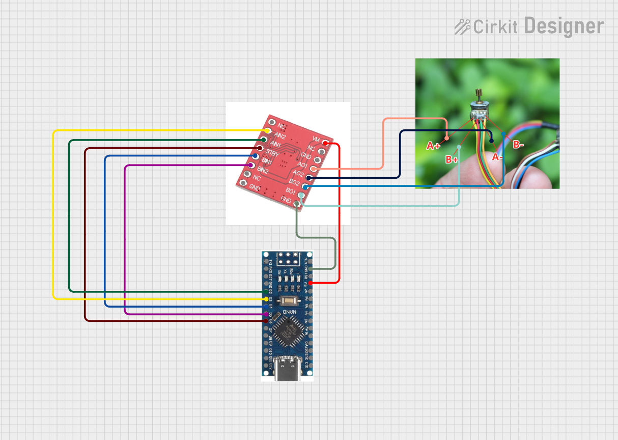
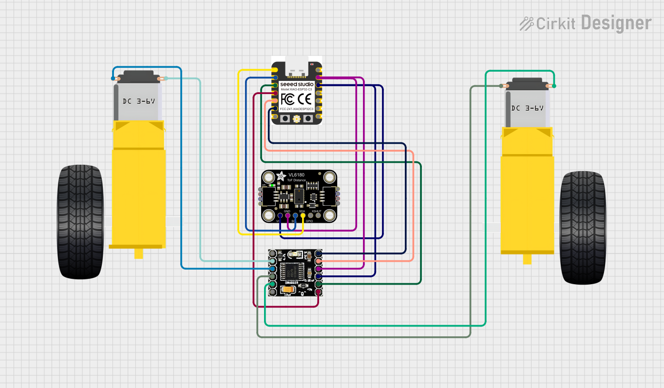

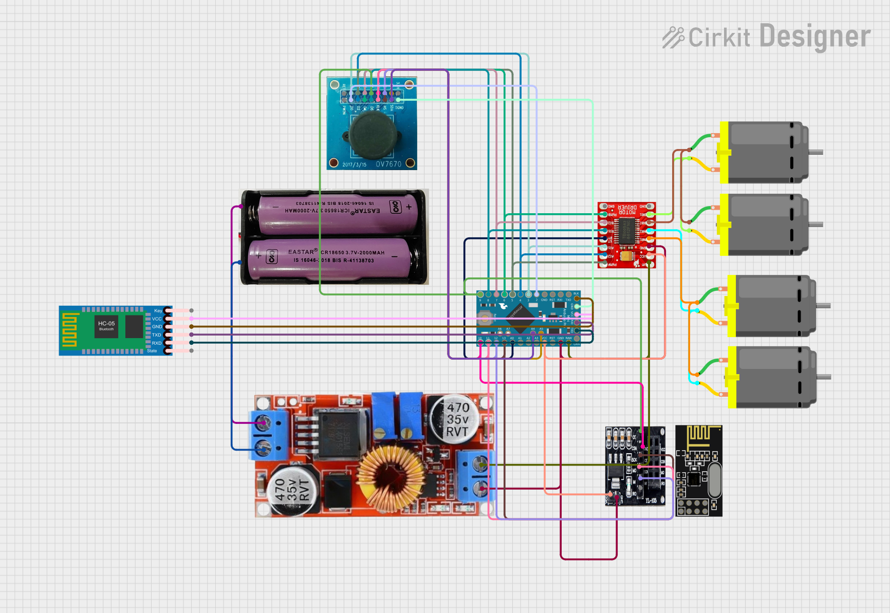
Explore Projects Built with DRV8834
Common Applications
- Robotics and automation systems
- 3D printers and CNC machines
- Camera gimbals and pan-tilt mechanisms
- Precision positioning systems
- Educational and DIY electronics projects
Technical Specifications
The following table outlines the key technical details of the DRV8834:
| Parameter | Value |
|---|---|
| Motor Supply Voltage (VMOT) | 2.5V to 10.8V |
| Logic Voltage (VCC) | 1.8V to 7V |
| Maximum Output Current | 1.5A per phase (continuous), 2A (peak) |
| Microstepping Modes | Full-step, half-step, 1/4-step, 1/8-step, 1/16-step, 1/32-step |
| Current Control | Adjustable via external potentiometer |
| Protection Features | Overcurrent, thermal shutdown, undervoltage lockout |
| Dimensions | 0.6" × 0.8" × 0.1" (15.2 mm × 20.3 mm × 2.7 mm) |
| Operating Temperature | -40°C to +85°C |
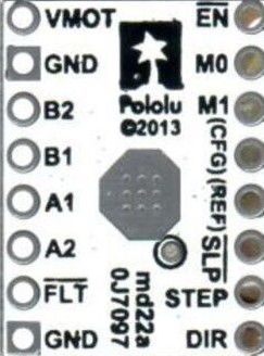
Pin Configuration and Descriptions
The DRV8834 has 16 pins, which are described in the table below:
| Pin | Name | Description |
|---|---|---|
| 1 | VMOT | Motor power supply (2.5V to 10.8V). Connect a decoupling capacitor close to this pin. |
| 2 | GND | Ground connection for motor power supply. |
| 3 | B2 | Output for motor coil B (phase 2). |
| 4 | B1 | Output for motor coil B (phase 1). |
| 5 | A1 | Output for motor coil A (phase 1). |
| 6 | A2 | Output for motor coil A (phase 2). |
| 7 | VCC | Logic power supply (1.8V to 7V). |
| 8 | GND | Ground connection for logic power supply. |
| 9 | STEP | Step input. A rising edge on this pin advances the motor by one step. |
| 10 | DIR | Direction input. High or low determines the rotation direction of the motor. |
| 11 | M0 | Microstepping mode selection input 0. |
| 12 | M1 | Microstepping mode selection input 1. |
| 13 | DECAY | Decay mode selection input. |
| 14 | FAULT | Fault output. Active low when a fault condition occurs. |
| 15 | SLEEP | Sleep mode input. Pull low to put the driver into low-power sleep mode. |
| 16 | ENABLE | Enable input. Pull low to disable the motor outputs. |
Usage Instructions
How to Use the DRV8834 in a Circuit
Power Connections:
- Connect the motor power supply (VMOT) to the VMOT pin and ground to the GND pin. Use a decoupling capacitor (e.g., 100 µF) close to the VMOT pin to reduce noise.
- Connect the logic power supply (VCC) to the VCC pin and ground to the GND pin.
Motor Connections:
- Connect the two coils of the stepper motor to the A1, A2, B1, and B2 pins. Ensure the correct pairing of the motor wires.
Control Inputs:
- Use the STEP pin to send step pulses to the driver. Each rising edge advances the motor by one step.
- Use the DIR pin to control the rotation direction of the motor.
- Configure the microstepping mode by setting the M0 and M1 pins according to the desired mode (refer to the datasheet for the mode selection table).
Current Limiting:
- Adjust the current limit using the onboard potentiometer. This prevents the motor from drawing excessive current and overheating.
Optional Features:
- Use the SLEEP pin to put the driver into low-power mode when not in use.
- Monitor the FAULT pin for error conditions such as overcurrent or thermal shutdown.
Example: Connecting the DRV8834 to an Arduino UNO
Below is an example of how to control a stepper motor using the DRV8834 and an Arduino UNO:
// Define pin connections
#define STEP_PIN 3  // Connect to the STEP pin of DRV8834
#define DIR_PIN 4   // Connect to the DIR pin of DRV8834

void setup() {
  pinMode(STEP_PIN, OUTPUT); // Set STEP pin as output
  pinMode(DIR_PIN, OUTPUT);  // Set DIR pin as output

  digitalWrite(DIR_PIN, LOW); // Set initial direction (LOW = clockwise)
}

void loop() {
  // Generate step pulses to move the motor
  digitalWrite(STEP_PIN, HIGH); // Set STEP pin HIGH
  delayMicroseconds(500);       // Wait 500 microseconds
  digitalWrite(STEP_PIN, LOW);  // Set STEP pin LOW
  delayMicroseconds(500);       // Wait 500 microseconds
}
Important Considerations
- Ensure the motor supply voltage (VMOT) and logic voltage (VCC) are within the specified ranges.
- Avoid connecting or disconnecting the motor while the driver is powered to prevent damage.
- Use appropriate heat dissipation methods if operating near the maximum current rating.
Troubleshooting and FAQs
Common Issues and Solutions
Motor Not Moving:
- Verify the STEP and DIR signals are being sent correctly.
- Check the motor connections to ensure proper wiring.
- Ensure the current limit is set appropriately for the motor.
Overheating:
- Reduce the current limit using the potentiometer.
- Improve heat dissipation by adding a heatsink or increasing airflow.
FAULT Pin Active (Low):
- Check for overcurrent or thermal shutdown conditions.
- Ensure the motor supply voltage is within the specified range.
Erratic Motor Movement:
- Verify the microstepping mode settings (M0 and M1 pins).
- Ensure the STEP signal timing meets the minimum pulse width requirements.
FAQs
Q: Can the DRV8834 drive unipolar stepper motors?
A: No, the DRV8834 is designed for bipolar stepper motors only.
Q: What is the maximum step rate supported by the DRV8834?
A: The maximum step rate depends on the STEP signal timing. Refer to the datasheet for the minimum pulse width requirements.
Q: Can I use the DRV8834 with a 12V motor?
A: No, the maximum motor supply voltage for the DRV8834 is 10.8V. Using a higher voltage may damage the driver.
Q: How do I reset the driver after a fault condition?
A: Toggle the SLEEP pin or cycle the power to reset the driver. Ensure the fault condition is resolved before restarting.