
How to Use ATMEGA128RFA1: Examples, Pinouts, and Specs

 Design with ATMEGA128RFA1 in Cirkit Designer
Introduction
The ATMEGA128RFA1 is a low-power microcontroller with an integrated 2.4 GHz transceiver, designed specifically for wireless communication applications. It combines the functionality of an 8-bit AVR microcontroller with a high-performance RF transceiver, making it an ideal choice for IoT devices, wireless sensor networks, and embedded systems. With 128 KB of flash memory, 4 KB of SRAM, and support for IEEE 802.15.4 communication protocols, the ATMEGA128RFA1 provides a versatile platform for developing low-power wireless solutions.
Explore Projects Built with ATMEGA128RFA1
 Open Project in Cirkit Designer
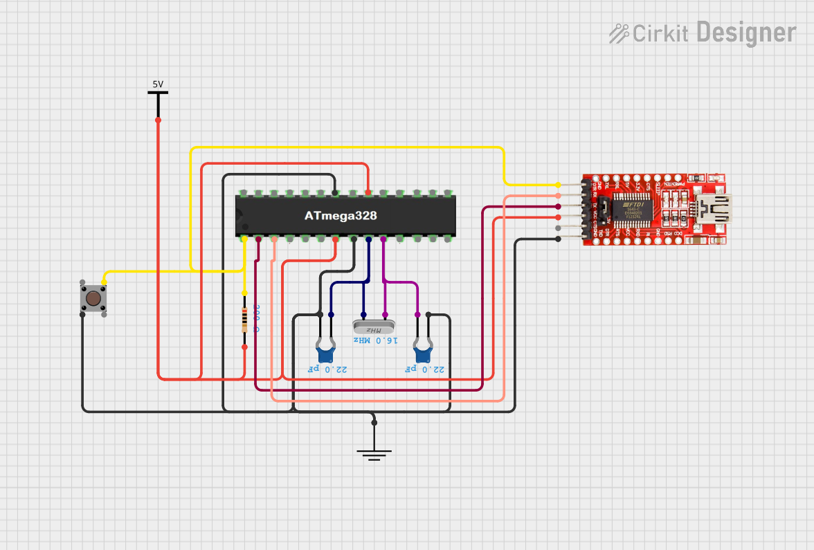 Open Project in Cirkit Designer
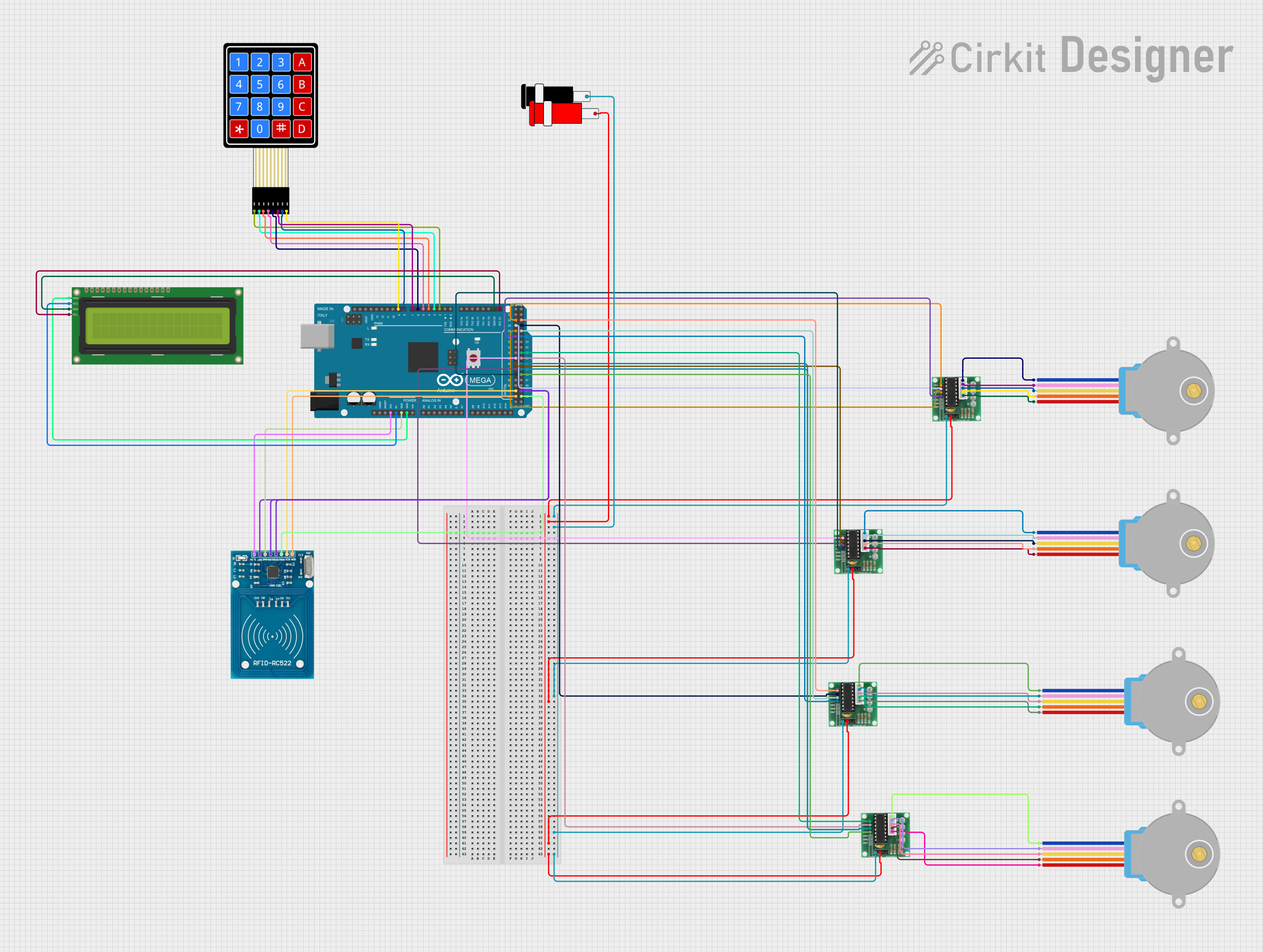 Open Project in Cirkit Designer
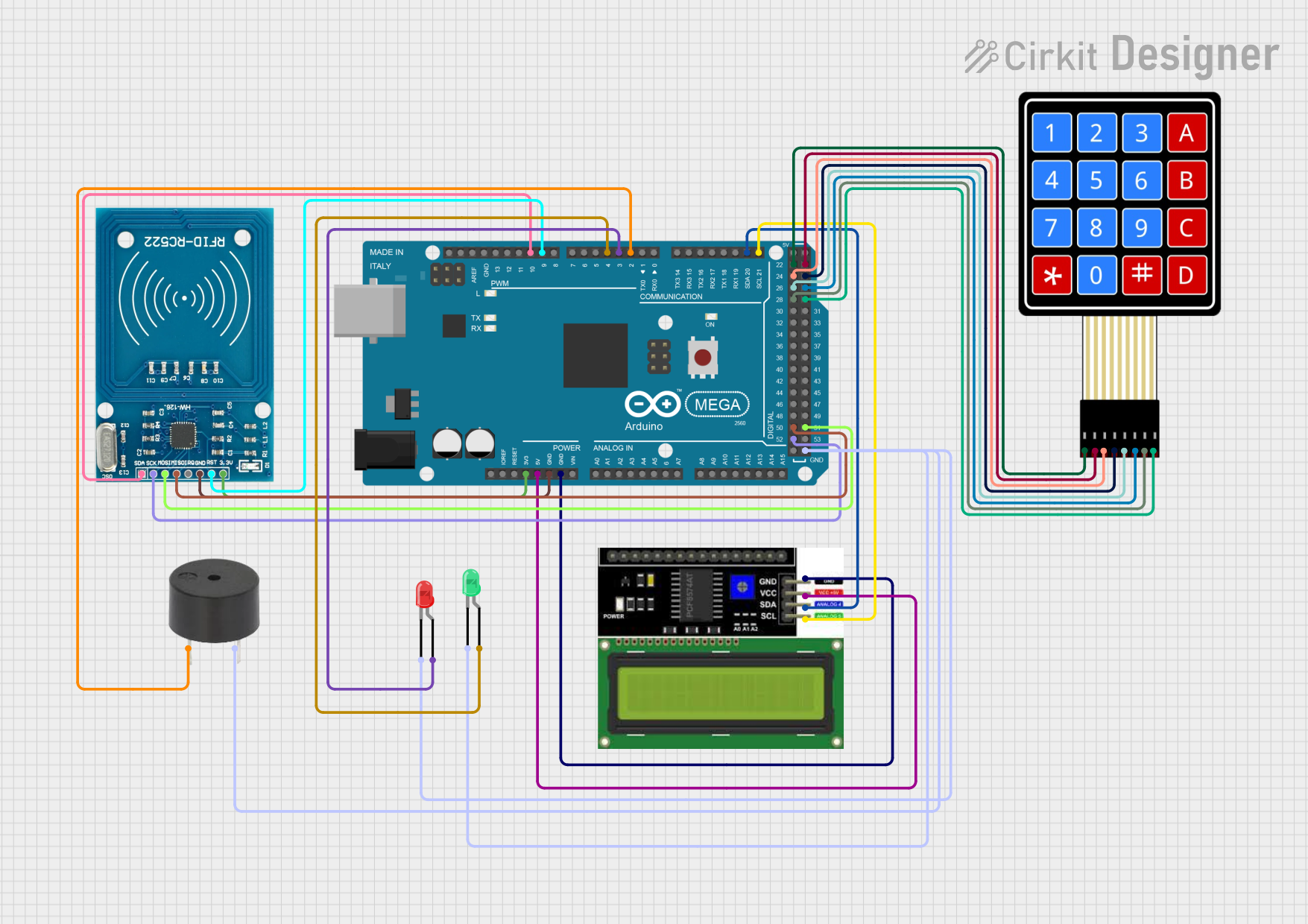 Open Project in Cirkit Designer
Explore Projects Built with ATMEGA128RFA1
Open Project in Cirkit DesignerOpen Project in Cirkit DesignerOpen Project in Cirkit DesignerOpen Project in Cirkit DesignerCommon Applications and Use Cases
- Wireless sensor networks
- Internet of Things (IoT) devices
- Home automation systems
- Industrial monitoring and control
- Smart metering
- Remote control systems
Technical Specifications
Key Technical Details
| Parameter | Value |
|---|---|
| Microcontroller Core | 8-bit AVR |
| Flash Memory | 128 KB |
| SRAM | 4 KB |
| EEPROM | 4 KB |
| Operating Voltage | 1.8V to 3.6V |
| RF Transceiver Frequency | 2.4 GHz |
| RF Data Rate | Up to 2 Mbps |
| Communication Protocols | IEEE 802.15.4, Zigbee, 6LoWPAN |
| GPIO Pins | 46 |
| ADC Resolution | 10-bit |
| Operating Temperature Range | -40°C to +85°C |
| Power Consumption (Active) | ~15 mA (transceiver active, MCU running) |
| Power Consumption (Sleep) | ~1 µA (deep sleep mode) |
Pin Configuration and Descriptions
The ATMEGA128RFA1 comes in a 64-pin TQFP/QFN package. Below is a summary of the key pins:
| Pin Number | Pin Name | Description |
|---|---|---|
| 1-8 | PA0-PA7 | General-purpose I/O pins (Port A) |
| 9-16 | PB0-PB7 | General-purpose I/O pins (Port B) |
| 17-24 | PC0-PC7 | General-purpose I/O pins (Port C) |
| 25-32 | PD0-PD7 | General-purpose I/O pins (Port D) |
| 33-40 | PE0-PE7 | General-purpose I/O pins (Port E) |
| 41-48 | PF0-PF7 | General-purpose I/O pins (Port F) |
| 49-56 | PG0-PG7 | General-purpose I/O pins (Port G) |
| 57 | VCC | Power supply (1.8V to 3.6V) |
| 58 | GND | Ground |
| 59 | RF_P | RF transceiver positive differential input |
| 60 | RF_N | RF transceiver negative differential input |
| 61 | RESET | Reset pin (active low) |
| 62 | XTAL1 | External clock/crystal input |
| 63 | XTAL2 | External clock/crystal output |
| 64 | AVCC | Analog power supply |
Usage Instructions
How to Use the ATMEGA128RFA1 in a Circuit
- Power Supply: Connect the VCC pin to a regulated power source (1.8V to 3.6V) and the GND pin to ground.
- Clock Source: Use an external crystal oscillator or clock source connected to the XTAL1 and XTAL2 pins for stable operation.
- Programming: Use an AVR programmer to upload firmware via the SPI interface.
- RF Antenna: Connect an appropriate 2.4 GHz antenna to the RF_P and RF_N pins for wireless communication.
- GPIO Configuration: Configure the GPIO pins as input or output as needed for your application.
- Communication Protocols: Implement IEEE 802.15.4 or other supported protocols in your firmware for wireless communication.
Important Considerations and Best Practices
- Power Management: Utilize the sleep modes to minimize power consumption in battery-powered applications.
- RF Design: Ensure proper impedance matching and PCB layout for the RF section to maximize signal strength and minimize interference.
- Decoupling Capacitors: Place decoupling capacitors close to the VCC and AVCC pins to reduce noise and improve stability.
- Firmware Development: Use Atmel Studio or other compatible IDEs for firmware development and debugging.
- Antenna Placement: Position the antenna away from noisy components and ground planes to improve RF performance.
Example Code for Arduino UNO
Although the ATMEGA128RFA1 is not directly compatible with Arduino UNO, you can use it with an external programmer. Below is an example of initializing the RF transceiver:
#include <avr/io.h>
#include <util/delay.h>

// Function to initialize the RF transceiver
void RF_Init() {
    // Set the transceiver to standby mode
    TRXPR = (1 << TRXRST); // Reset the transceiver
    _delay_ms(1);          // Wait for the reset to complete

    // Configure the transceiver for IEEE 802.15.4
    TRX_CTRL_1 = 0x20;     // Set TX_AUTO_CRC_ON for automatic CRC
    PHY_TX_PWR = 0x00;     // Set transmission power to maximum
    PHY_CC_CCA = 0x20;     // Set channel to 20 (2.4 GHz band)
}

// Main function
int main(void) {
    RF_Init();             // Initialize the RF transceiver

    while (1) {
        // Main loop
    }

    return 0;
}
Troubleshooting and FAQs
Common Issues and Solutions
Microcontroller Not Responding
- Cause: Incorrect power supply or missing decoupling capacitors.
- Solution: Verify the power supply voltage and ensure proper decoupling capacitors are in place.
RF Communication Fails
- Cause: Poor antenna design or incorrect RF settings.
- Solution: Check the antenna connection and ensure the RF settings (e.g., channel, power) match the intended configuration.
High Power Consumption
- Cause: Microcontroller not entering sleep mode.
- Solution: Implement proper power management in the firmware to utilize sleep modes.
Programming Errors
- Cause: Incorrect SPI connections or incompatible programmer.
- Solution: Verify the SPI connections and use a compatible AVR programmer.
FAQs
Q: Can the ATMEGA128RFA1 be used with Zigbee?
A: Yes, the ATMEGA128RFA1 supports IEEE 802.15.4, which is the foundation for Zigbee communication.
Q: What is the maximum range of the RF transceiver?
A: The range depends on the antenna design and environmental factors but typically ranges from 30 to 100 meters in open space.
Q: How do I reduce power consumption in my design?
A: Use the microcontroller's sleep modes and optimize the RF transceiver's duty cycle to minimize power usage.
Q: Can I use the ATMEGA128RFA1 with an Arduino IDE?
A: While the ATMEGA128RFA1 is not natively supported by the Arduino IDE, you can use it with custom board definitions and an external programmer.