How to Use 3x 3.7V Battery: Examples, Pinouts, and Specs
Introduction
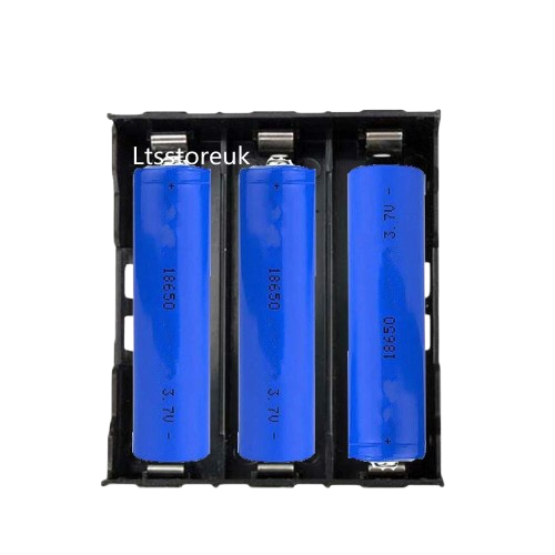
The 3x 3.7V Battery pack is a power source consisting of three lithium-ion cells, each with a nominal voltage of 3.7 volts. This configuration is commonly used in portable electronic devices, robotics, and DIY projects due to its high energy density, lightweight design, and rechargeable nature. The battery pack can be connected in series or parallel, depending on the desired voltage and capacity requirements.
Explore Projects Built with 3x 3.7V Battery

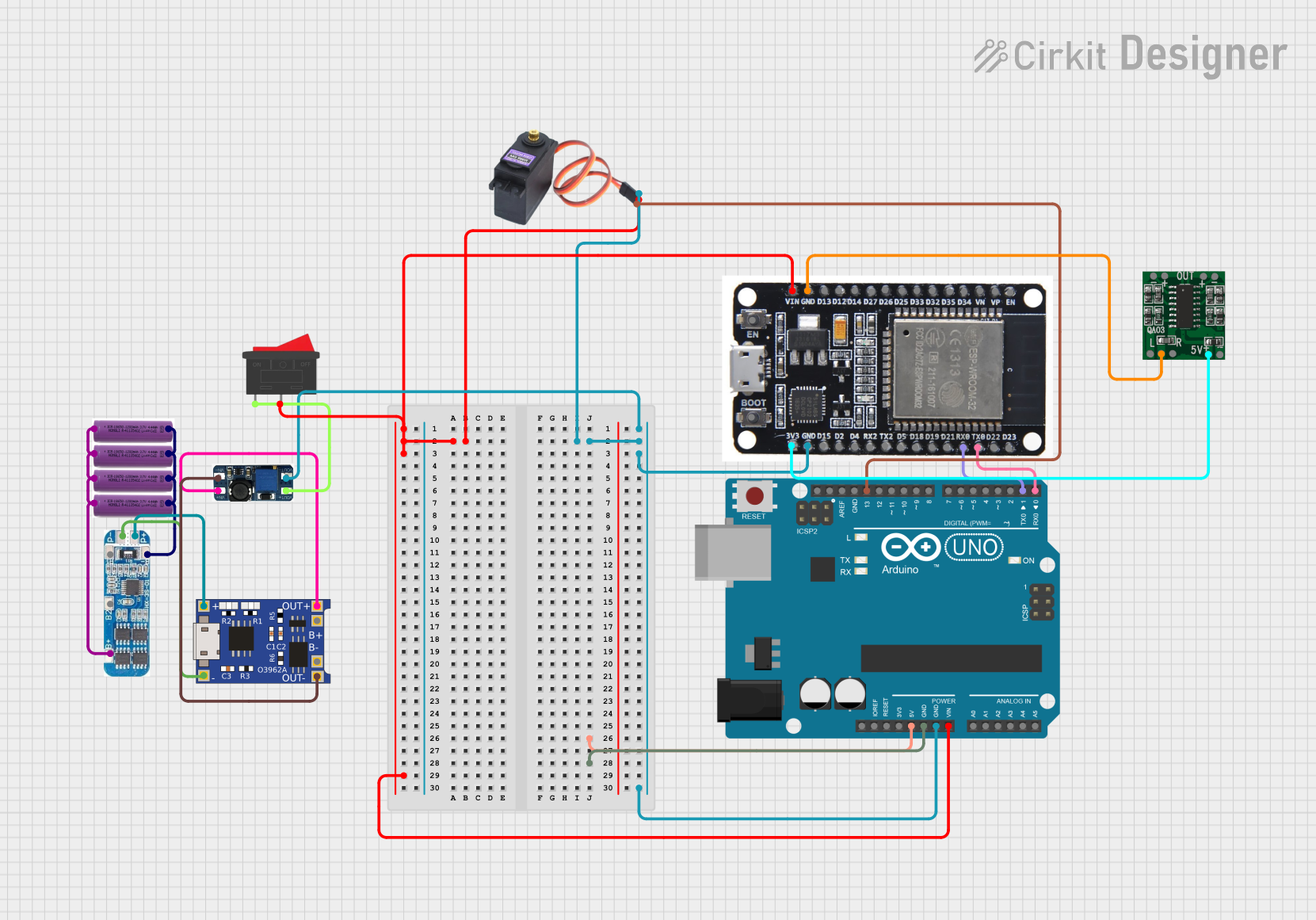
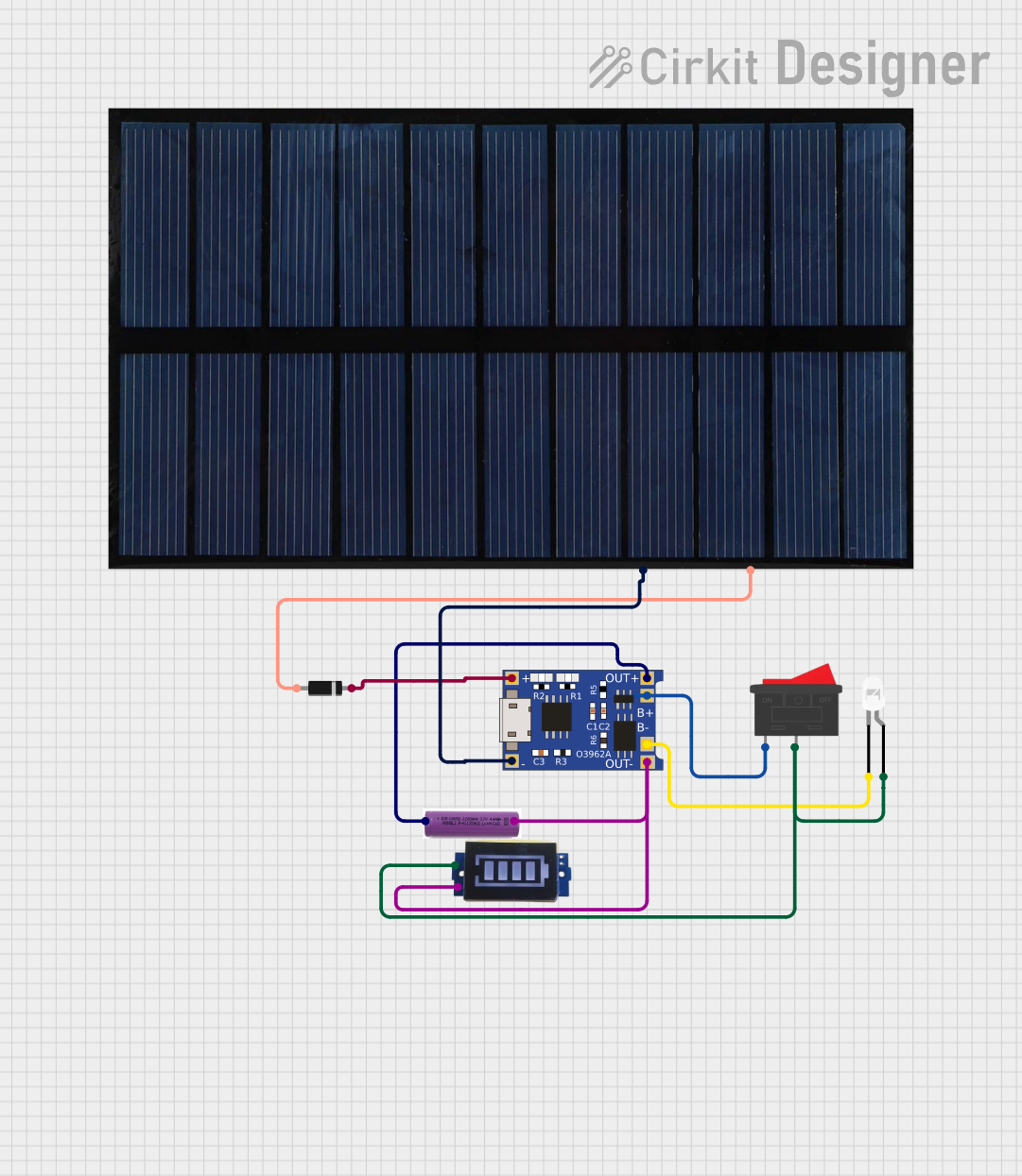
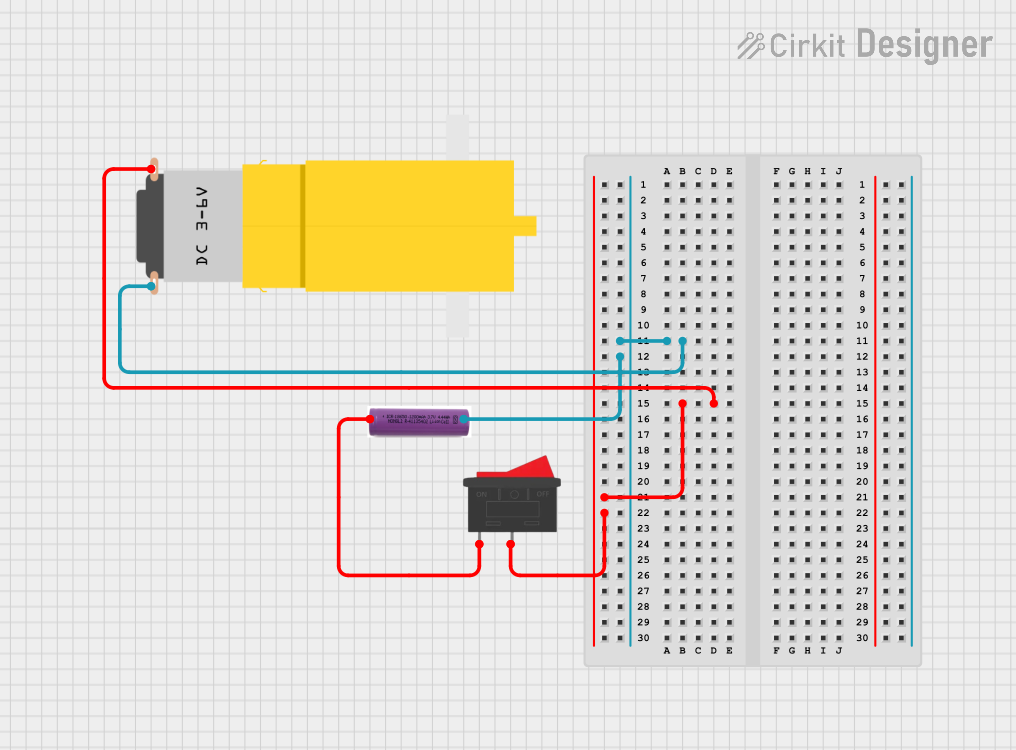
Explore Projects Built with 3x 3.7V Battery
Common Applications
- Powering portable electronic devices (e.g., handheld tools, flashlights)
- Robotics and remote-controlled vehicles
- DIY electronics projects
- Backup power supplies for small systems
- Wearable technology
Technical Specifications
Below are the key technical details for the 3x 3.7V Battery pack:
| Parameter | Value |
|---|---|
| Nominal Voltage | 3.7V per cell (11.1V in series) |
| Capacity (Typical) | 2000–5000mAh (varies by model) |
| Configuration | 3 cells (series or parallel) |
| Maximum Charge Voltage | 4.2V per cell (12.6V in series) |
| Discharge Cutoff Voltage | 3.0V per cell (9.0V in series) |
| Maximum Discharge Current | 10A (varies by model) |
| Chemistry | Lithium-Ion (Li-Ion) |
| Weight | ~150–250g (varies by capacity) |
| Dimensions | Varies by model |
Pin Configuration and Descriptions
The battery pack typically has two or three terminals, depending on the design. Below is a general description:
| Pin | Label | Description |
|---|---|---|
| 1 | + (Positive) | Positive terminal for power output |
| 2 | - (Negative) | Negative terminal for power output |
| 3 | BMS (Optional) | Connection to Battery Management System (if present) |
Note: Some battery packs include a built-in Battery Management System (BMS) for overcharge, over-discharge, and short-circuit protection.
Usage Instructions
How to Use the Battery Pack in a Circuit
- Determine the Configuration: Decide whether to use the battery pack in series (for higher voltage) or parallel (for higher capacity). Most pre-assembled packs are configured in series for a total voltage of 11.1V.
- Connect to a Load: Use the positive (+) and negative (-) terminals to connect the battery pack to your circuit. Ensure the load does not exceed the maximum discharge current.
- Charging the Battery:
- Use a compatible lithium-ion battery charger with a maximum output voltage of 12.6V (for a 3S configuration).
- Ensure the charger supports the required charging current (typically 1C or less, where C is the battery capacity in Ah).
Important Considerations and Best Practices
- Avoid Overcharging: Never exceed 4.2V per cell (12.6V for the pack). Overcharging can damage the cells or cause safety hazards.
- Avoid Over-Discharging: Do not let the voltage drop below 3.0V per cell (9.0V for the pack). This can permanently damage the battery.
- Use a BMS: If the battery pack does not include a built-in Battery Management System, consider adding one to protect against overcharge, over-discharge, and short circuits.
- Monitor Temperature: Avoid using the battery in environments above 60°C or below -20°C.
- Storage: Store the battery at ~50% charge in a cool, dry place if not in use for extended periods.
Example: Connecting to an Arduino UNO
The 3x 3.7V Battery pack can be used to power an Arduino UNO via its VIN pin. Below is an example:
- Connect the positive terminal of the battery pack to the VIN pin of the Arduino.
- Connect the negative terminal of the battery pack to the GND pin of the Arduino.
Sample Code for Monitoring Battery Voltage
You can use a voltage divider circuit to measure the battery voltage with the Arduino's analog input. Here's an example:
// Define the analog pin for voltage measurement
const int voltagePin = A0;

// Voltage divider resistor values (in ohms)
const float R1 = 10000.0; // Resistor connected to battery positive
const float R2 = 10000.0; // Resistor connected to ground

// Reference voltage of Arduino (5V for most boards)
const float referenceVoltage = 5.0;

void setup() {
  Serial.begin(9600); // Initialize serial communication
}

void loop() {
  // Read the analog value (0-1023)
  int analogValue = analogRead(voltagePin);

  // Calculate the input voltage using the voltage divider formula
  float batteryVoltage = (analogValue / 1023.0) * referenceVoltage * ((R1 + R2) / R2);

  // Print the battery voltage to the Serial Monitor
  Serial.print("Battery Voltage: ");
  Serial.print(batteryVoltage);
  Serial.println(" V");

  delay(1000); // Wait for 1 second before the next reading
}
Note: Adjust the resistor values (R1 and R2) based on your circuit design to ensure the voltage does not exceed the Arduino's input limits.
Troubleshooting and FAQs
Common Issues
Battery Not Charging
- Cause: Faulty charger or damaged battery cells.
- Solution: Verify the charger output voltage and current. Check for physical damage to the battery.
Battery Drains Quickly
- Cause: Over-discharge or aging cells.
- Solution: Avoid discharging below 3.0V per cell. Replace the battery if it has degraded significantly.
Battery Overheats
- Cause: Excessive current draw or charging in a hot environment.
- Solution: Ensure the load does not exceed the maximum discharge current. Charge in a cool environment.
Arduino Not Powering On
- Cause: Insufficient voltage or incorrect wiring.
- Solution: Verify the battery voltage is above 7V (minimum for VIN pin). Check connections.
FAQs
Q: Can I use this battery pack to power a 12V motor?
A: Yes, but ensure the motor's current draw does not exceed the battery's maximum discharge current.
Q: How do I know when the battery is fully charged?
A: A fully charged 3x 3.7V battery pack will have a voltage of approximately 12.6V.
Q: Can I connect multiple battery packs together?
A: Yes, you can connect packs in series or parallel, but ensure they are of the same capacity and charge level to avoid imbalances.
Q: Is it safe to leave the battery connected to the charger?
A: No, disconnect the charger once the battery is fully charged to prevent overcharging.
By following this documentation, you can safely and effectively use the 3x 3.7V Battery pack in your projects.