How to Use Kontaktor : Examples, Pinouts, and Specs
Introduction
A kontaktor is an electromechanical switch designed to control high-power circuits using low-power signals. Manufactured by Schneider, the High Volt kontaktor is a reliable and robust solution for industrial applications. It is commonly used to switch electrical loads such as motors, lighting systems, heating elements, and other high-power devices. Its ability to handle high currents and voltages makes it an essential component in automation and power distribution systems.
Explore Projects Built with Kontaktor


Explore Projects Built with Kontaktor
Common Applications
- Motor control in industrial machinery
- Switching high-power lighting systems
- HVAC systems
- Power distribution in industrial plants
- Automation systems for controlling heavy electrical loads
Technical Specifications
Key Specifications
| Parameter | Value |
|---|---|
| Manufacturer | Schneider |
| Part ID | High Volt |
| Rated Operating Voltage | 24V DC (coil), 690V AC (load) |
| Rated Current | 32A |
| Number of Poles | 3 (Three-phase) |
| Coil Power Consumption | 8W |
| Mechanical Durability | 10 million operations |
| Electrical Durability | 1 million operations |
| Operating Temperature | -25°C to +60°C |
| Mounting Type | DIN Rail or Panel Mount |
Pin Configuration and Descriptions
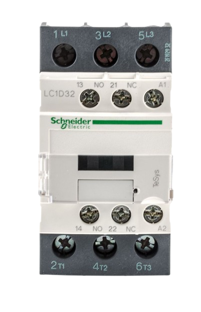
The High Volt kontaktor has the following pin configuration:
Power Terminals
| Terminal Label | Description |
|---|---|
| L1, L2, L3 | Input terminals for three-phase AC |
| T1, T2, T3 | Output terminals for three-phase AC |
Control Terminals
| Terminal Label | Description |
|---|---|
| A1 | Positive terminal for the coil |
| A2 | Negative terminal for the coil |
Auxiliary Contacts (Optional)
| Terminal Label | Description |
|---|---|
| NO (Normally Open) | Auxiliary contact for control circuits |
| NC (Normally Closed) | Auxiliary contact for control circuits |
Usage Instructions
How to Use the Kontaktor in a Circuit
Power Connections:
- Connect the three-phase AC input to the terminals L1, L2, L3.
- Connect the load (e.g., motor, lighting) to the output terminals T1, T2, T3.
Control Circuit:
- Connect the control voltage (e.g., 24V DC) to the coil terminals A1 and A2.
- Ensure the control circuit includes a switch or relay to activate the coil.
Auxiliary Contacts (if applicable):
- Use the NO or NC auxiliary contacts for additional control or feedback in the circuit.
Mounting:
- Secure the kontaktor to a DIN rail or panel using the provided mounting hardware.
Important Considerations
- Voltage and Current Ratings: Ensure the load does not exceed the rated voltage (690V AC) or current (32A).
- Coil Voltage: Verify that the control voltage matches the coil's rated voltage (24V DC).
- Overload Protection: Use appropriate fuses or circuit breakers to protect the circuit.
- Noise Suppression: Install a surge suppressor across the coil terminals to reduce electrical noise.
- Wiring: Use appropriately rated wires for both the power and control circuits.
Example: Connecting to an Arduino UNO
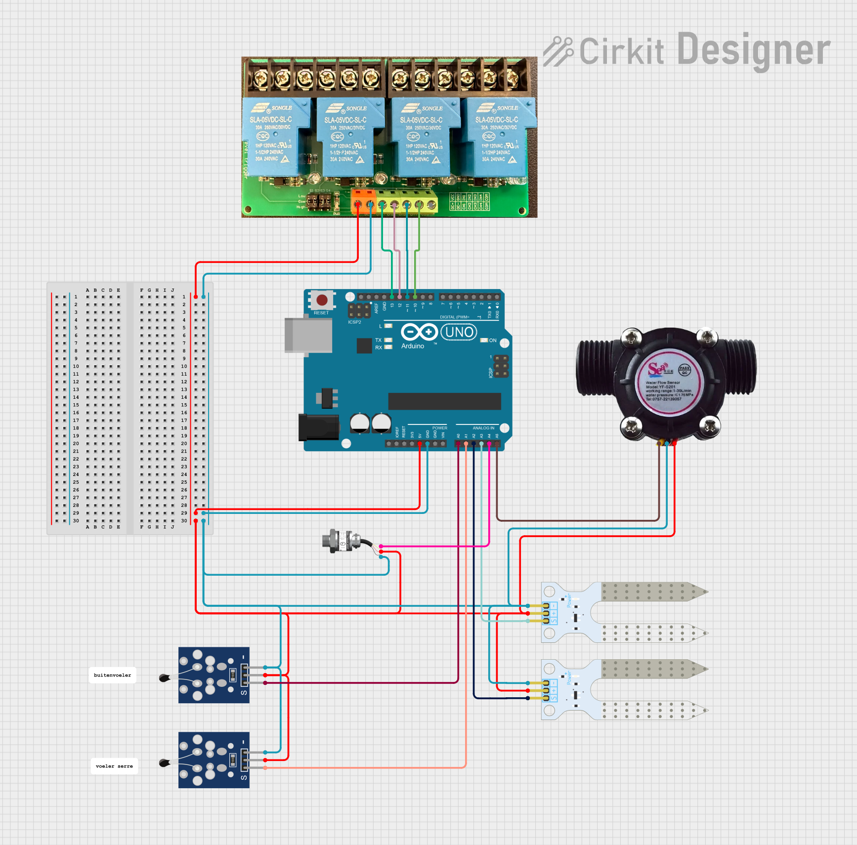
The High Volt kontaktor can be controlled using an Arduino UNO and a relay module. Below is an example circuit and code:
Circuit Description
- The Arduino controls a relay module, which in turn activates the kontaktor's coil.
- The relay module isolates the Arduino from the high-power circuit.
Arduino Code
// Define the pin connected to the relay module
const int relayPin = 7;

void setup() {
  // Set the relay pin as an output
  pinMode(relayPin, OUTPUT);
  // Ensure the relay is off at startup
  digitalWrite(relayPin, LOW);
}

void loop() {
  // Turn on the relay (activates the kontaktor)
  digitalWrite(relayPin, HIGH);
  delay(5000); // Keep the kontaktor on for 5 seconds

  // Turn off the relay (deactivates the kontaktor)
  digitalWrite(relayPin, LOW);
  delay(5000); // Wait for 5 seconds before repeating
}
Best Practices
- Always disconnect power before wiring or servicing the kontaktor.
- Regularly inspect the contacts for wear and replace them if necessary.
- Use proper insulation and grounding to ensure safety.
Troubleshooting and FAQs
Common Issues and Solutions
| Issue | Possible Cause | Solution |
|---|---|---|
| Kontaktor does not activate | Coil voltage is incorrect or missing | Verify the control voltage at A1/A2. |
| Contacts are overheating | Load exceeds rated current | Reduce the load or use a higher-rated kontaktor. |
| Excessive noise during operation | Electrical noise or coil surge | Install a surge suppressor across the coil. |
| Auxiliary contacts not working | Miswiring or damaged contacts | Check wiring and replace damaged contacts. |
FAQs
Can the High Volt kontaktor be used for single-phase loads?
- Yes, connect the single-phase load to one of the poles (e.g., L1 and T1).
What is the purpose of auxiliary contacts?
- Auxiliary contacts provide feedback or control signals for automation systems.
How do I know if the coil is damaged?
- Measure the resistance across A1 and A2. If it is open or significantly different from the specified value, the coil may be damaged.
By following this documentation, you can effectively use the Schneider High Volt kontaktor in your projects and ensure reliable operation.