Cirkit Designer Logo
Cirkit Designer
Your all-in-one circuit design IDE
Home / 
Component Documentation

How to Use Adafruit PN532 Breakout: Examples, Pinouts, and Specs

Image of Adafruit PN532 Breakout
Cirkit Designer LogoDesign with Adafruit PN532 Breakout in Cirkit Designer

Introduction

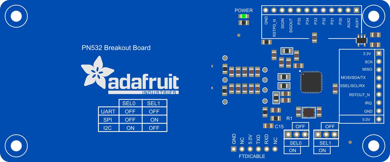
The Adafruit PN532 Breakout Board is a versatile and user-friendly NFC/RFID controller that enables wireless communication for a variety of applications. Based on the widely-used PN532 chip, this breakout board is designed to read and write NFC tags, interface with NFC-enabled devices, and facilitate secure transactions. With an onboard 3.3V regulator and level shifting, it is compatible with a broad range of microcontrollers, including both 3.3V and 5V systems, such as the Arduino UNO.

Explore Projects Built with Adafruit PN532 Breakout

Use Cirkit Designer to design, explore, and prototype these projects online. Some projects support real-time simulation. Click "Open Project" to start designing instantly!
Biometric and RFID Security System with Dual Adafruit Feather nRF52840 Controllers
Image of Rfid access control: A project utilizing Adafruit PN532 Breakout in a practical application
This circuit features two Adafruit Feather nRF52840 microcontrollers, each interfaced with an RFID-RC522 module for RFID communication and an AT24C256 external EEPROM for additional memory storage. One of the microcontrollers is also connected to an R307 Fingerprint Sensor for biometric input, and both microcontrollers are powered by a shared power supply and a coin cell breakout for backup or RTC power. The circuit is likely designed for secure access control or identification purposes, utilizing both RFID and fingerprint authentication, with data storage capabilities.
Cirkit Designer LogoOpen Project in Cirkit Designer
Battery-Powered Smart Sensor Hub with Adafruit QT Py RP2040
Image of wearable final: A project utilizing Adafruit PN532 Breakout in a practical application
This circuit features an Adafruit QT Py RP2040 microcontroller interfaced with an APDS9960 proximity sensor, an MPU6050 accelerometer and gyroscope, and an OLED display via I2C communication. It also includes a buzzer controlled by the microcontroller and is powered by a 3.7V LiPo battery with a toggle switch for power control.
Cirkit Designer LogoOpen Project in Cirkit Designer
Arduino Nano Controlled Smart Relay with APDS-9960 Gesture Sensor
Image of contactless smart switch: A project utilizing Adafruit PN532 Breakout in a practical application
This circuit features an Arduino Nano microcontroller interfaced with an Adafruit APDS-9960 sensor and a 2-channel relay module. The APDS-9960 sensor, which is capable of gesture detection, is connected to the Arduino via I2C communication lines (SCL, SDA) and powered by the Arduino's 3.3V output. The relay module is controlled by the Arduino through a digital pin (D7) and is used to switch an AC-powered bulb on and off, with the relay's common (COM) terminal connected to the AC source and the normally open (NO1) terminal connected to the bulb.
Cirkit Designer LogoOpen Project in Cirkit Designer
Battery-Powered Smart Light with Proximity Sensor and OLED Display using Adafruit QT Py RP2040
Image of lab: A project utilizing Adafruit PN532 Breakout in a practical application
This circuit is a portable, battery-powered system featuring an Adafruit QT Py RP2040 microcontroller that interfaces with an OLED display, a proximity sensor, an accelerometer, and an RGB LED strip. The system is powered by a lithium-ion battery with a step-up boost converter to provide 5V for the LED strip, and it includes a toggle switch for power control. The microcontroller communicates with the sensors and display via I2C.
Cirkit Designer LogoOpen Project in Cirkit Designer

Explore Projects Built with Adafruit PN532 Breakout

Use Cirkit Designer to design, explore, and prototype these projects online. Some projects support real-time simulation. Click "Open Project" to start designing instantly!
Image of Rfid access control: A project utilizing Adafruit PN532 Breakout in a practical application
Biometric and RFID Security System with Dual Adafruit Feather nRF52840 Controllers
This circuit features two Adafruit Feather nRF52840 microcontrollers, each interfaced with an RFID-RC522 module for RFID communication and an AT24C256 external EEPROM for additional memory storage. One of the microcontrollers is also connected to an R307 Fingerprint Sensor for biometric input, and both microcontrollers are powered by a shared power supply and a coin cell breakout for backup or RTC power. The circuit is likely designed for secure access control or identification purposes, utilizing both RFID and fingerprint authentication, with data storage capabilities.
Cirkit Designer LogoOpen Project in Cirkit Designer
Image of wearable final: A project utilizing Adafruit PN532 Breakout in a practical application
Battery-Powered Smart Sensor Hub with Adafruit QT Py RP2040
This circuit features an Adafruit QT Py RP2040 microcontroller interfaced with an APDS9960 proximity sensor, an MPU6050 accelerometer and gyroscope, and an OLED display via I2C communication. It also includes a buzzer controlled by the microcontroller and is powered by a 3.7V LiPo battery with a toggle switch for power control.
Cirkit Designer LogoOpen Project in Cirkit Designer
Image of contactless smart switch: A project utilizing Adafruit PN532 Breakout in a practical application
Arduino Nano Controlled Smart Relay with APDS-9960 Gesture Sensor
This circuit features an Arduino Nano microcontroller interfaced with an Adafruit APDS-9960 sensor and a 2-channel relay module. The APDS-9960 sensor, which is capable of gesture detection, is connected to the Arduino via I2C communication lines (SCL, SDA) and powered by the Arduino's 3.3V output. The relay module is controlled by the Arduino through a digital pin (D7) and is used to switch an AC-powered bulb on and off, with the relay's common (COM) terminal connected to the AC source and the normally open (NO1) terminal connected to the bulb.
Cirkit Designer LogoOpen Project in Cirkit Designer
Image of lab: A project utilizing Adafruit PN532 Breakout in a practical application
Battery-Powered Smart Light with Proximity Sensor and OLED Display using Adafruit QT Py RP2040
This circuit is a portable, battery-powered system featuring an Adafruit QT Py RP2040 microcontroller that interfaces with an OLED display, a proximity sensor, an accelerometer, and an RGB LED strip. The system is powered by a lithium-ion battery with a step-up boost converter to provide 5V for the LED strip, and it includes a toggle switch for power control. The microcontroller communicates with the sensors and display via I2C.
Cirkit Designer LogoOpen Project in Cirkit Designer

Common Applications and Use Cases

  • Contactless payment systems
  • Access control
  • Identification and authentication
  • NFC tag reading and writing
  • Peer-to-peer communication between NFC devices

Technical Specifications

Key Technical Details

  • Operating Voltage: 3.3V to 5V (with onboard regulator)
  • Operating Current: 100mA (typical)
  • Frequency: 13.56MHz
  • Supported Protocols: ISO/IEC 14443 Type A and B, FeliCa, and MIFARE cards
  • Interface: I2C, SPI, and HSU (High-Speed UART)
  • Range: Up to 7cm (depending on antenna geometry and card type)

Pin Configuration and Descriptions

Pin Number Name Description
1 VCC Power supply (3.3V-5V)
2 GND Ground connection
3 SDA I2C Data / SPI MOSI
4 SCL I2C Clock / SPI Clock
5 MISO SPI MISO (not used in I2C mode)
6 IRQ Interrupt pin (active low)
7 RSTO Reset output from PN532
8 RSTPD_N Reset input to PN532 (active low)

Usage Instructions

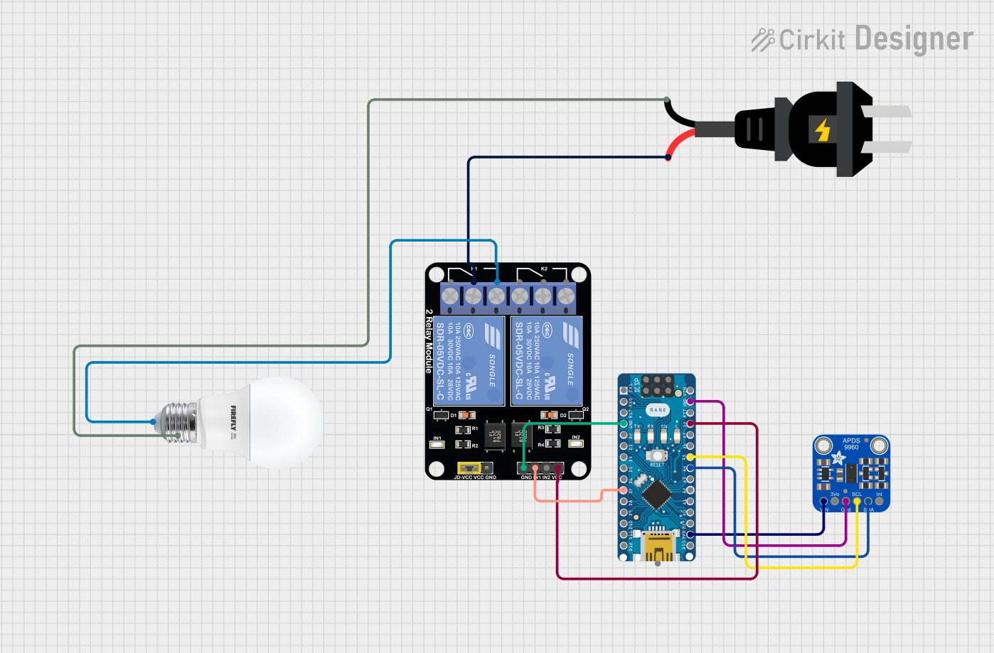
How to Use the Component in a Circuit

  1. Power Connections: Connect VCC to a 3.3V or 5V supply and GND to the ground of your microcontroller.
  2. Data Connections: Choose between I2C, SPI, or HSU for communication and connect the respective pins to your microcontroller.
  3. Antenna: Ensure the antenna area is unobstructed for optimal range.
  4. Reset: Connect RSTPD_N to a digital pin for manual reset control, if required.

Important Considerations and Best Practices

  • Use level shifting for 5V microcontrollers to protect the PN532.
  • Place the breakout board away from metal surfaces to avoid interference.
  • For I2C communication, ensure pull-up resistors are in place if not already provided by your microcontroller.
  • Avoid bending the antenna or subjecting it to physical stress.

Example Code for Arduino UNO

#include <Wire.h>
#include <Adafruit_PN532.h>

// If using the I2C interface, define SDA and SCL pins
#define SDA_PIN 2
#define SCL_PIN 3

// Create an instance of the Adafruit_PN532 class
Adafruit_PN532 nfc(SDA_PIN, SCL_PIN);

void setup(void) {
  Serial.begin(115200);
  Serial.println("Hello! Scan a NFC tag!");

  nfc.begin();

  uint32_t versiondata = nfc.getFirmwareVersion();
  if (!versiondata) {
    Serial.print("Didn't find PN53x board");
    while (1); // halt
  }

  // Configure board to read RFID tags
  nfc.SAMConfig();
}

void loop(void) {
  uint8_t success;
  uint8_t uid[] = { 0, 0, 0, 0, 0, 0, 0 }; // Buffer to store the returned UID
  uint8_t uidLength; // Length of the UID (4 or 7 bytes depending on ISO14443A card type)

  // Wait for an ISO14443A type card (Mifare, etc.). When one is found, 'uid' will be populated
  success = nfc.readPassiveTargetID(PN532_MIFARE_ISO14443A, uid, &uidLength);

  if (success) {
    // Display some basic information about the card
    Serial.println("Found an ISO14443A card");
    Serial.print("UID Length: ");Serial.print(uidLength, DEC);Serial.println(" bytes");
    Serial.print("UID Value: ");
    for (uint8_t i=0; i < uidLength; i++) {
      Serial.print(" 0x");Serial.print(uid[i], HEX);
    }
    Serial.println("");
    // Wait 1 second before continuing
    delay(1000);
  }
}

Troubleshooting and FAQs

Common Issues Users Might Face

  • No response from the module: Ensure power connections are correct and the microcontroller pins are properly configured.
  • Inconsistent tag reads: Check for any obstructions or interference near the antenna area.
  • Communication errors: Verify the correct interface (I2C/SPI/HSU) is selected and properly connected.

Solutions and Tips for Troubleshooting

  • Double-check wiring, especially the SDA and SCL lines for I2C, and MOSI, MISO, and SCK for SPI.
  • Ensure the library used matches the communication protocol selected.
  • Reset the PN532 module using the RSTPD_N pin if the module becomes unresponsive.

FAQs

Q: Can the Adafruit PN532 Breakout Board be used with a 5V microcontroller like an Arduino UNO?

A: Yes, the board has a built-in level shifter and regulator, making it compatible with 5V systems.

Q: What is the maximum range of the NFC communication?

A: The maximum range is up to 7cm, but this can vary based on antenna design and environmental factors.

Q: How do I know if the board is powered and functioning correctly?

A: Upon powering up, the board's firmware version can be read as a basic check. If the firmware version is returned, the board is functioning correctly.

Q: Can the board read all types of NFC tags?

A: The board supports a wide range of NFC tags, including ISO/IEC 14443 Type A and B, FeliCa, and MIFARE cards. However, compatibility with all NFC tag types is not guaranteed.