
How to Use Driver Motor l293D: Examples, Pinouts, and Specs
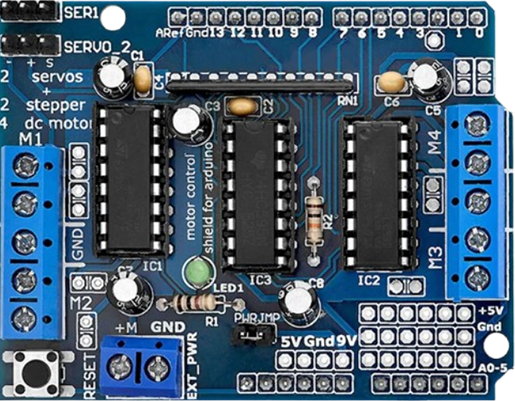
 Design with Driver Motor l293D in Cirkit Designer
Introduction
The L293D is a dual H-bridge motor driver IC manufactured by AD Store (Part ID: L293D). It is designed to control the direction and speed of DC motors and stepper motors. This versatile IC can drive two motors simultaneously, making it a popular choice for robotics, automation, and motor control projects. Its compact design and ease of use make it ideal for hobbyists and professionals alike.
Explore Projects Built with Driver Motor l293D
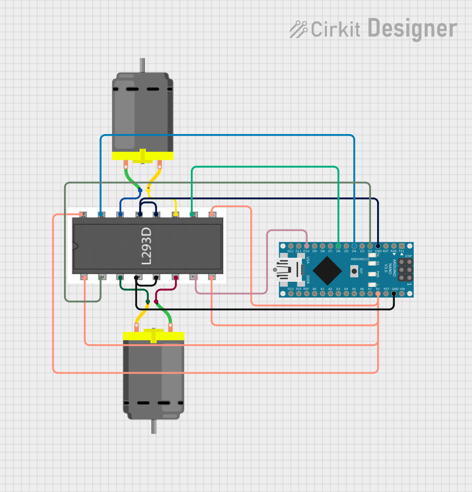 Open Project in Cirkit Designer
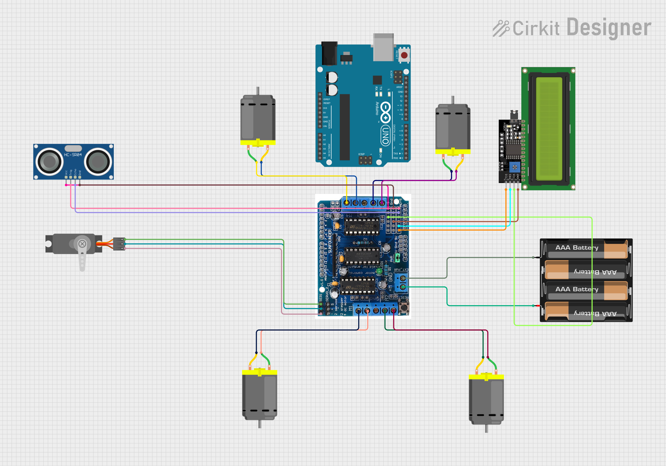 Open Project in Cirkit Designer
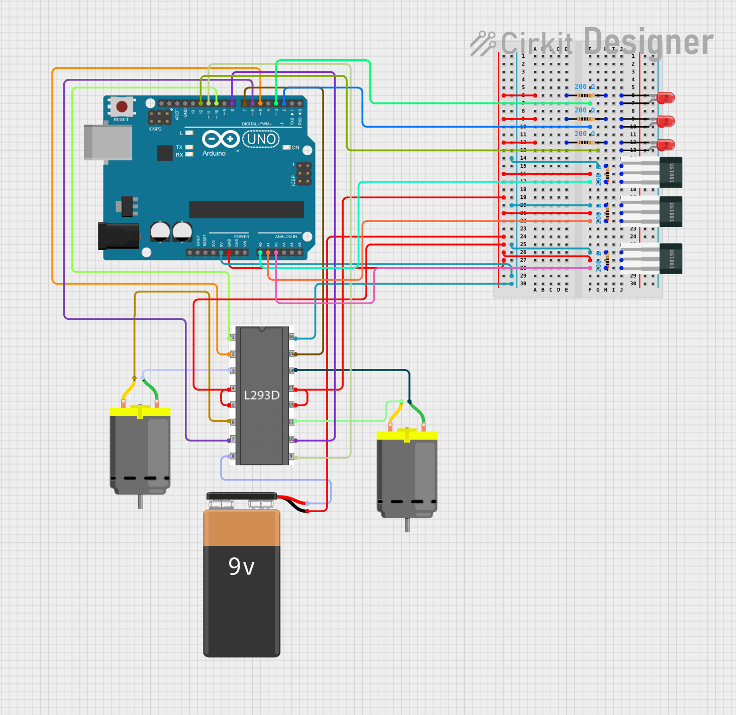 Open Project in Cirkit Designer
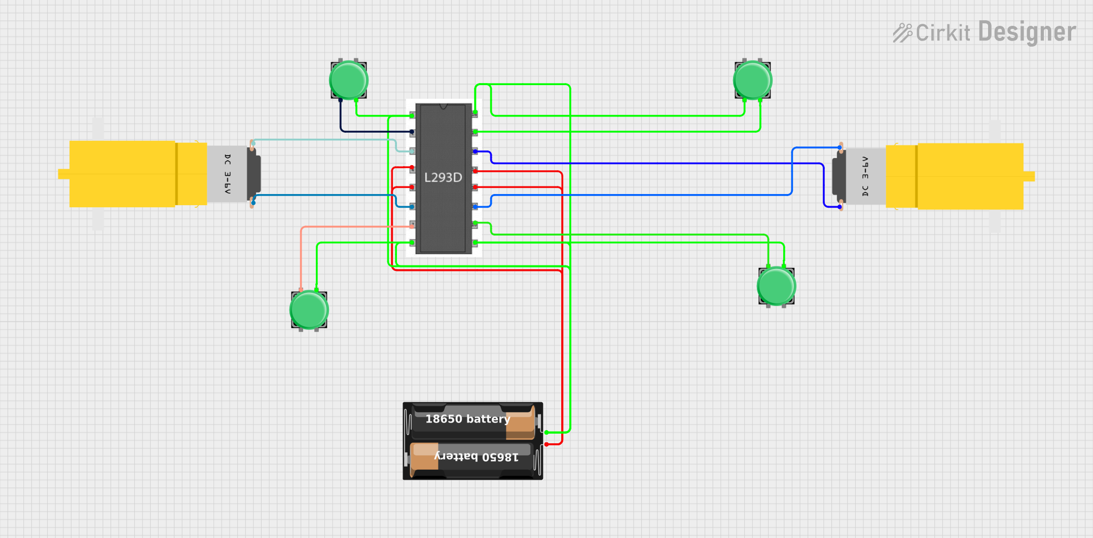 Open Project in Cirkit Designer
Explore Projects Built with Driver Motor l293D
Open Project in Cirkit DesignerOpen Project in Cirkit DesignerOpen Project in Cirkit DesignerOpen Project in Cirkit DesignerCommon Applications
- Robotics (e.g., controlling wheels or robotic arms)
- Automation systems
- Conveyor belts
- Stepper motor control
- DIY motorized projects
Technical Specifications
The L293D is a robust IC with the following key specifications:
| Parameter | Value |
|---|---|
| Supply Voltage (Vcc1) | 4.5V to 7V |
| Motor Supply Voltage (Vcc2) | 4.5V to 36V |
| Output Current (per channel) | 600mA (peak: 1.2A) |
| Logic Input Voltage | 0V to 7V |
| Operating Temperature | -40°C to +150°C |
| Number of Channels | 2 (dual H-bridge) |
| Maximum Power Dissipation | 5W |
Pin Configuration and Descriptions
The L293D IC has 16 pins, each serving a specific function. Below is the pinout and description:
| Pin Number | Pin Name | Description |
|---|---|---|
| 1 | Enable 1,2 | Enables H-bridge 1 (active HIGH). |
| 2 | Input 1 | Logic input for H-bridge 1 (controls motor direction). |
| 3 | Output 1 | Output for H-bridge 1 (connect to motor terminal). |
| 4 | Ground (GND) | Ground connection. |
| 5 | Ground (GND) | Ground connection. |
| 6 | Output 2 | Output for H-bridge 1 (connect to motor terminal). |
| 7 | Input 2 | Logic input for H-bridge 1 (controls motor direction). |
| 8 | Vcc2 (Motor Vcc) | Supply voltage for motors (4.5V to 36V). |
| 9 | Enable 3,4 | Enables H-bridge 2 (active HIGH). |
| 10 | Input 3 | Logic input for H-bridge 2 (controls motor direction). |
| 11 | Output 3 | Output for H-bridge 2 (connect to motor terminal). |
| 12 | Ground (GND) | Ground connection. |
| 13 | Ground (GND) | Ground connection. |
| 14 | Output 4 | Output for H-bridge 2 (connect to motor terminal). |
| 15 | Input 4 | Logic input for H-bridge 2 (controls motor direction). |
| 16 | Vcc1 (Logic Vcc) | Supply voltage for logic circuitry (4.5V to 7V). |
Usage Instructions
How to Use the L293D in a Circuit
- Power Supply: Connect pin 16 (Vcc1) to a 5V supply for the logic circuitry and pin 8 (Vcc2) to the motor's supply voltage (4.5V to 36V).
- Ground Connections: Connect all ground pins (4, 5, 12, 13) to the common ground of the circuit.
- Motor Connections: Connect the motor terminals to the output pins (3 and 6 for motor 1, 11 and 14 for motor 2).
- Control Inputs: Use the input pins (2, 7 for motor 1; 10, 15 for motor 2) to control the motor's direction. Apply HIGH or LOW signals to these pins.
- Enable Pins: Ensure the enable pins (1 for motor 1, 9 for motor 2) are set HIGH to activate the respective H-bridge.
Important Considerations
- Heat Dissipation: The IC can get hot during operation. Use a heat sink if driving motors at high currents.
- Flyback Diodes: The L293D has internal flyback diodes to protect against voltage spikes, so external diodes are not required.
- Current Limitation: Ensure the motor's current does not exceed the IC's maximum rating (600mA continuous, 1.2A peak).
Example: Connecting L293D to Arduino UNO
Below is an example of how to control a DC motor using the L293D and Arduino UNO:
Circuit Connections
- Connect pin 16 (Vcc1) to the Arduino's 5V pin.
- Connect pin 8 (Vcc2) to an external power supply (e.g., 9V for the motor).
- Connect pin 4, 5, 12, and 13 to the Arduino's GND.
- Connect motor terminals to pins 3 and 6.
- Connect pin 2 to Arduino digital pin 9 and pin 7 to Arduino digital pin 10.
- Connect pin 1 (Enable 1,2) to Arduino digital pin 8.
Arduino Code
// Define motor control pins
const int enablePin = 8; // Enable pin for motor 1
const int input1 = 9;    // Input 1 for motor 1
const int input2 = 10;   // Input 2 for motor 1

void setup() {
  // Set pin modes
  pinMode(enablePin, OUTPUT);
  pinMode(input1, OUTPUT);
  pinMode(input2, OUTPUT);

  // Initialize motor in stopped state
  digitalWrite(enablePin, LOW); // Disable motor
  digitalWrite(input1, LOW);    // Set input1 LOW
  digitalWrite(input2, LOW);    // Set input2 LOW
}

void loop() {
  // Example: Rotate motor clockwise
  digitalWrite(enablePin, HIGH); // Enable motor
  digitalWrite(input1, HIGH);    // Set input1 HIGH
  digitalWrite(input2, LOW);     // Set input2 LOW
  delay(2000);                   // Run motor for 2 seconds

  // Example: Rotate motor counterclockwise
  digitalWrite(input1, LOW);     // Set input1 LOW
  digitalWrite(input2, HIGH);    // Set input2 HIGH
  delay(2000);                   // Run motor for 2 seconds

  // Stop motor
  digitalWrite(enablePin, LOW);  // Disable motor
  delay(2000);                   // Wait for 2 seconds
}
Troubleshooting and FAQs
Common Issues
Motor Not Running:
- Ensure the enable pin is set HIGH.
- Verify the motor's power supply (Vcc2) is connected and within the specified range.
- Check the input pins for proper HIGH/LOW signals.
Overheating:
- Ensure the motor's current does not exceed the IC's maximum rating.
- Use a heat sink if necessary.
Erratic Motor Behavior:
- Check for loose connections in the circuit.
- Ensure the ground connections are properly shared between the IC, motor, and control board.
FAQs
Can the L293D drive stepper motors?
- Yes, the L293D can control stepper motors by driving the coils in sequence. Use both H-bridges for this purpose.
Do I need external diodes for protection?
- No, the L293D has built-in flyback diodes to protect against voltage spikes.
What is the maximum motor voltage the L293D can handle?
- The motor supply voltage (Vcc2) can range from 4.5V to 36V.
Can I control the motor speed with the L293D?
- Yes, use PWM (Pulse Width Modulation) on the enable pins to control motor speed.
By following this documentation, you can effectively use the L293D motor driver IC in your projects.