How to Use EG800K-CN v2: Examples, Pinouts, and Specs

 Design with EG800K-CN v2 in Cirkit Designer
Introduction
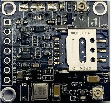
The EG800K-CN v2 is a high-performance DC-DC converter module manufactured by Arduino, with the part ID "UNO". This module is designed for efficient power conversion, offering adjustable output voltage and current capabilities. It is ideal for powering microcontrollers, sensors, and other low-power devices in a variety of electronic applications.
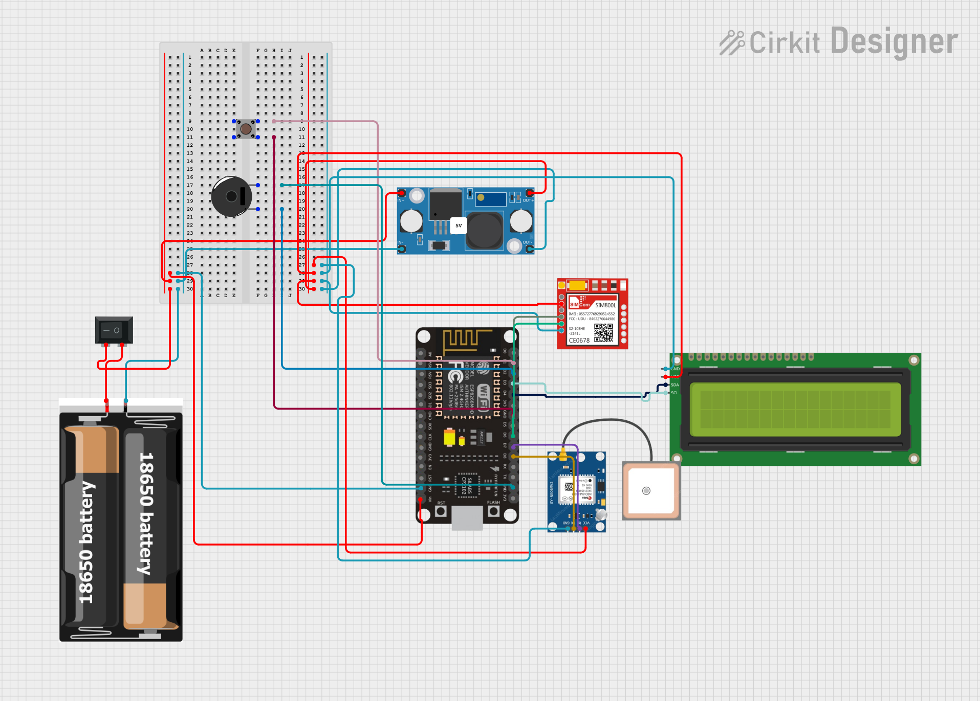
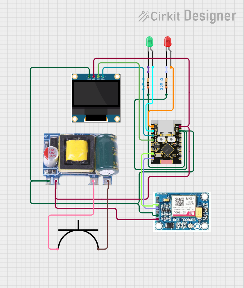
Explore Projects Built with EG800K-CN v2

 Open Project in Cirkit Designer
 Open Project in Cirkit Designer
 Open Project in Cirkit Designer
 Open Project in Cirkit Designer
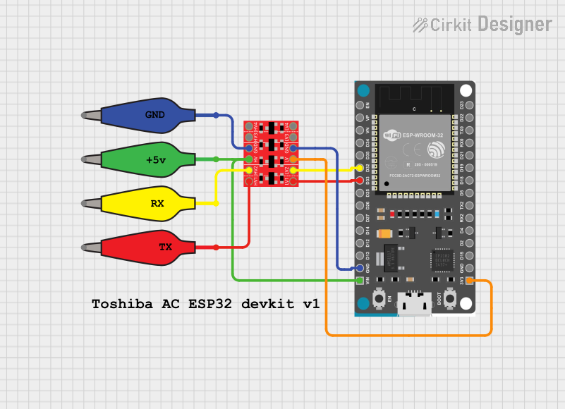
Explore Projects Built with EG800K-CN v2

 Open Project in Cirkit Designer
 Open Project in Cirkit Designer
 Open Project in Cirkit Designer
 Open Project in Cirkit Designer
Common Applications and Use Cases
- Powering Arduino boards and other microcontrollers
- Supplying power to sensors and actuators in IoT projects
- Battery-powered systems requiring voltage regulation
- Prototyping and development of low-power electronic devices
- Robotics and automation systems
Technical Specifications
The EG800K-CN v2 is designed to provide reliable and efficient power conversion. Below are its key technical details:
General Specifications
| Parameter | Value |
|---|---|
| Input Voltage Range | 6V to 36V |
| Output Voltage Range | 1.25V to 32V (adjustable) |
| Maximum Output Current | 5A (with proper heat dissipation) |
| Output Power | Up to 75W |
| Efficiency | Up to 96% |
| Operating Temperature | -40°C to +85°C |
| Dimensions | 60mm x 21mm x 15mm |
Pin Configuration and Descriptions
| Pin Name | Description |
|---|---|
| VIN+ | Positive input voltage terminal |
| VIN- | Negative input voltage terminal (ground) |
| VOUT+ | Positive output voltage terminal |
| VOUT- | Negative output voltage terminal (ground) |
| ADJ | Adjustable pin for setting output voltage |
Usage Instructions
The EG800K-CN v2 is straightforward to use in a circuit. Follow the steps below to integrate it into your project:
Step 1: Connect the Input Voltage
- Connect the VIN+ pin to the positive terminal of your power source.
- Connect the VIN- pin to the ground terminal of your power source.
- Ensure the input voltage is within the specified range (6V to 36V).
Step 2: Adjust the Output Voltage
- Use a small screwdriver to turn the potentiometer on the module.
- Turning clockwise increases the output voltage.
- Turning counterclockwise decreases the output voltage.
- Measure the output voltage across the VOUT+ and VOUT- pins using a multimeter.
Step 3: Connect the Load
- Connect the VOUT+ pin to the positive terminal of your load (e.g., Arduino UNO).
- Connect the VOUT- pin to the ground terminal of your load.
Important Considerations
- Heat Dissipation: If the output current exceeds 3A, ensure proper heat dissipation by attaching a heatsink or using active cooling.
- Polarity: Double-check the polarity of all connections to avoid damaging the module.
- Current Limiting: If your load requires less current, adjust the current limit using the onboard potentiometer (if available).
Example: Powering an Arduino UNO
To power an Arduino UNO with the EG800K-CN v2:
- Set the output voltage to 5V using the potentiometer.
- Connect the VOUT+ pin to the Arduino's 5V pin.
- Connect the VOUT- pin to the Arduino's GND pin.
Arduino Code Example
If you are using the EG800K-CN v2 to power sensors connected to an Arduino UNO, here is a simple example:
// Example: Reading a sensor value and printing it to the Serial Monitor
const int sensorPin = A0; // Sensor connected to analog pin A0
int sensorValue = 0;      // Variable to store the sensor reading

void setup() {
  Serial.begin(9600); // Initialize serial communication at 9600 baud
}

void loop() {
  sensorValue = analogRead(sensorPin); // Read the sensor value
  Serial.print("Sensor Value: ");      // Print label to Serial Monitor
  Serial.println(sensorValue);        // Print the sensor value
  delay(1000);                         // Wait for 1 second before next reading
}
Troubleshooting and FAQs
Common Issues and Solutions
No Output Voltage
- Cause: Input voltage is not connected or is below the minimum required.
- Solution: Verify the input voltage is within the 6V to 36V range and check connections.
Output Voltage is Incorrect
- Cause: Potentiometer is not adjusted correctly.
- Solution: Use a multimeter to measure and adjust the output voltage.
Module Overheats
- Cause: Excessive current draw or insufficient heat dissipation.
- Solution: Reduce the load current or attach a heatsink to the module.
Load Does Not Power On
- Cause: Incorrect polarity or loose connections.
- Solution: Double-check all connections and ensure correct polarity.
FAQs
Q1: Can the EG800K-CN v2 be used with a battery?
A1: Yes, it can be used with a battery as long as the input voltage is within the 6V to 36V range.
Q2: How do I limit the output current?
A2: Use the onboard current adjustment potentiometer (if available) to set the desired current limit.
Q3: Is the module protected against short circuits?
A3: The module includes basic protection features, but it is recommended to avoid short circuits to prevent damage.
Q4: Can I use this module to power a 3.3V device?
A4: Yes, adjust the output voltage to 3.3V using the potentiometer before connecting your device.