Cirkit Designer Logo
Cirkit Designer
Your all-in-one circuit design IDE
Home / 
Component Documentation

How to Use NodeMCU ESP8266 (ESP-12E): Examples, Pinouts, and Specs
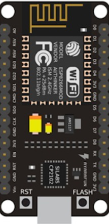

Image of NodeMCU ESP8266 (ESP-12E)
Cirkit Designer LogoDesign with NodeMCU ESP8266 (ESP-12E) in Cirkit Designer

Introduction

The NodeMCU ESP8266 (ESP-12E) is a low-cost, open-source IoT platform based on the ESP8266 Wi-Fi module. It features a built-in microcontroller, USB interface for programming, and compatibility with the Arduino IDE, making it an excellent choice for IoT projects. With its integrated Wi-Fi capabilities, the NodeMCU ESP8266 allows seamless connectivity to the internet, enabling remote monitoring and control of devices.

Explore Projects Built with NodeMCU ESP8266 (ESP-12E)
Use Cirkit Designer to design, explore, and prototype these projects online. Some projects support real-time simulation. Click "Open Project" to start designing instantly!
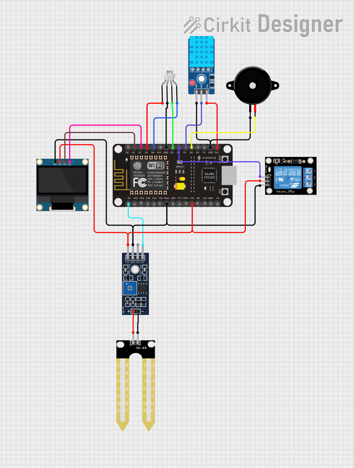
ESP8266 NodeMCU Controlled Environmental Monitoring System with OLED Display and Relay Switching
Image of soil moisture: A project utilizing NodeMCU ESP8266 (ESP-12E) in a practical application
This circuit features an ESP8266 NodeMCU microcontroller connected to various peripherals. It includes a DHT11 sensor for temperature and humidity readings, a YL-83 module with YL-69 probe for soil moisture detection, a 0.96" OLED display for data output, a common cathode RGB LED for status indication, a piezo speaker for audio alerts, and a KY-019 relay module for controlling external loads. The NodeMCU facilitates data acquisition from sensors, drives the display and LED, and can trigger the relay and speaker based on sensor inputs or programmed conditions.
Cirkit Designer LogoOpen Project in Cirkit Designer
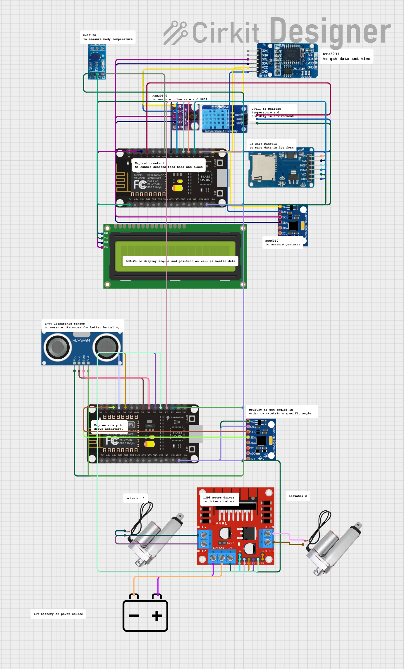
ESP8266 NodeMCU-Based Multifunctional Sensor Platform with Wi-Fi and Data Logging
Image of smart electric bed: A project utilizing NodeMCU ESP8266 (ESP-12E) in a practical application
This circuit features an ESP8266 NodeMCU as the central microcontroller, interfacing with a variety of sensors and modules via I2C, digital, and analog connections. It includes an RTC DS3231 for real-time clock functionality, a MAX30100 pulse oximeter, two MPU-6050 gyro/accelerometers, a DHT11 temperature and humidity sensor, a DS18B20 temperature sensor, and an I2C LCD for display. The circuit also controls a micro SD card module for data logging, an HC-SR04 ultrasonic sensor for distance measurement, and two linear actuators via an L298N motor driver, powered by a 12V battery. The ESP8266 NodeMCU's GPIOs are used for interfacing with these components, and two NodeMCUs are connected via serial communication (TX/RX).
Cirkit Designer LogoOpen Project in Cirkit Designer
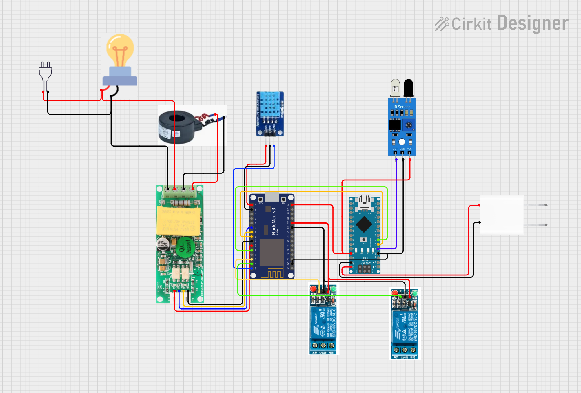
NodeMCU ESP8266 and Arduino Nano Based Smart Energy Monitoring System with IR Control
Image of SCADA: A project utilizing NodeMCU ESP8266 (ESP-12E) in a practical application
This circuit features a NodeMCU V3 ESP8266 microcontroller interfaced with a PZEM004T power monitoring module, a DHT11 temperature and humidity sensor, and two 5V relays for controlling external devices. The NodeMCU collects environmental data and power consumption metrics, and can control the relays based on this data or external inputs from an IR sensor. An Arduino Nano is also present, powered by a 5V adapter, and is connected to the NodeMCU and IR sensor, suggesting a secondary control or processing function within the system.
Cirkit Designer LogoOpen Project in Cirkit Designer
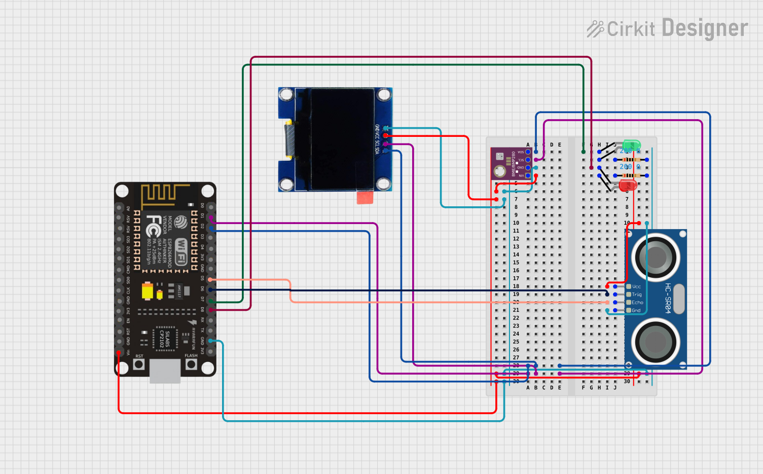
ESP8266 NodeMCU-Based Environmental Monitoring and Proximity Detection System
Image of mgr: A project utilizing NodeMCU ESP8266 (ESP-12E) in a practical application
This circuit features an ESP8266 NodeMCU microcontroller interfaced with a BME/BMP280 sensor for environmental data, an HC-SR04 ultrasonic sensor for distance measurement, and an OLED display for output. Two LEDs (red and green) are included, each with a current-limiting resistor, likely for status indication. The ESP8266 facilitates communication with the sensors and display via I2C (SCL and SDA lines) and controls the LEDs and reads from the ultrasonic sensor using its GPIO pins.
Cirkit Designer LogoOpen Project in Cirkit Designer

Explore Projects Built with NodeMCU ESP8266 (ESP-12E)

Use Cirkit Designer to design, explore, and prototype these projects online. Some projects support real-time simulation. Click "Open Project" to start designing instantly!
Image of soil moisture: A project utilizing NodeMCU ESP8266 (ESP-12E) in a practical application
ESP8266 NodeMCU Controlled Environmental Monitoring System with OLED Display and Relay Switching
This circuit features an ESP8266 NodeMCU microcontroller connected to various peripherals. It includes a DHT11 sensor for temperature and humidity readings, a YL-83 module with YL-69 probe for soil moisture detection, a 0.96" OLED display for data output, a common cathode RGB LED for status indication, a piezo speaker for audio alerts, and a KY-019 relay module for controlling external loads. The NodeMCU facilitates data acquisition from sensors, drives the display and LED, and can trigger the relay and speaker based on sensor inputs or programmed conditions.
Cirkit Designer LogoOpen Project in Cirkit Designer
Image of smart electric bed: A project utilizing NodeMCU ESP8266 (ESP-12E) in a practical application
ESP8266 NodeMCU-Based Multifunctional Sensor Platform with Wi-Fi and Data Logging
This circuit features an ESP8266 NodeMCU as the central microcontroller, interfacing with a variety of sensors and modules via I2C, digital, and analog connections. It includes an RTC DS3231 for real-time clock functionality, a MAX30100 pulse oximeter, two MPU-6050 gyro/accelerometers, a DHT11 temperature and humidity sensor, a DS18B20 temperature sensor, and an I2C LCD for display. The circuit also controls a micro SD card module for data logging, an HC-SR04 ultrasonic sensor for distance measurement, and two linear actuators via an L298N motor driver, powered by a 12V battery. The ESP8266 NodeMCU's GPIOs are used for interfacing with these components, and two NodeMCUs are connected via serial communication (TX/RX).
Cirkit Designer LogoOpen Project in Cirkit Designer
Image of SCADA: A project utilizing NodeMCU ESP8266 (ESP-12E) in a practical application
NodeMCU ESP8266 and Arduino Nano Based Smart Energy Monitoring System with IR Control
This circuit features a NodeMCU V3 ESP8266 microcontroller interfaced with a PZEM004T power monitoring module, a DHT11 temperature and humidity sensor, and two 5V relays for controlling external devices. The NodeMCU collects environmental data and power consumption metrics, and can control the relays based on this data or external inputs from an IR sensor. An Arduino Nano is also present, powered by a 5V adapter, and is connected to the NodeMCU and IR sensor, suggesting a secondary control or processing function within the system.
Cirkit Designer LogoOpen Project in Cirkit Designer
Image of mgr: A project utilizing NodeMCU ESP8266 (ESP-12E) in a practical application
ESP8266 NodeMCU-Based Environmental Monitoring and Proximity Detection System
This circuit features an ESP8266 NodeMCU microcontroller interfaced with a BME/BMP280 sensor for environmental data, an HC-SR04 ultrasonic sensor for distance measurement, and an OLED display for output. Two LEDs (red and green) are included, each with a current-limiting resistor, likely for status indication. The ESP8266 facilitates communication with the sensors and display via I2C (SCL and SDA lines) and controls the LEDs and reads from the ultrasonic sensor using its GPIO pins.
Cirkit Designer LogoOpen Project in Cirkit Designer

Common Applications and Use Cases

  • Home automation systems
  • IoT-enabled sensors and devices
  • Wireless data logging
  • Smart appliances
  • Prototyping and educational projects

Technical Specifications

Key Technical Details

Specification Value
Microcontroller ESP8266 (Tensilica L106 32-bit)
Operating Voltage 3.3V
Input Voltage (VIN) 4.5V - 10V
Flash Memory 4MB (ESP-12E module)
Clock Speed 80 MHz (up to 160 MHz)
Digital I/O Pins 11
Analog Input Pins 1 (10-bit ADC, 0-3.3V range)
Wi-Fi Standard 802.11 b/g/n
USB Interface Micro-USB
Power Consumption ~70mA (idle), ~200mA (Wi-Fi TX)
Dimensions 58mm x 31mm x 13mm

Pin Configuration and Descriptions

Pin Name Pin Number Description
VIN - Input voltage pin (4.5V - 10V). Used to power the board externally.
GND - Ground pin. Connect to the ground of the circuit.
3V3 - 3.3V output pin. Provides regulated 3.3V power.
D0-D8 GPIO 16-0 General-purpose digital I/O pins. Can be used for PWM, I2C, SPI, etc.
A0 - Analog input pin (0-3.3V range).
RX GPIO 3 UART receive pin. Used for serial communication.
TX GPIO 1 UART transmit pin. Used for serial communication.
EN - Enable pin. Pull high to enable the module.
RST - Reset pin. Pull low to reset the module.

Usage Instructions

How to Use the NodeMCU ESP8266 in a Circuit

  1. Powering the Board:

    • Use the micro-USB port to power the NodeMCU via a USB cable.
    • Alternatively, supply 4.5V-10V to the VIN pin and connect GND to the ground of your power source.
  2. Programming the Board:

    • Install the Arduino IDE and add the ESP8266 board package via the Board Manager.
    • Select "NodeMCU 1.0 (ESP-12E Module)" from the Tools > Board menu.
    • Connect the NodeMCU to your computer using a USB cable.
    • Write your code in the Arduino IDE and upload it to the board.
  3. Connecting Peripherals:

    • Use the GPIO pins (D0-D8) for digital input/output.
    • Connect sensors or other analog devices to the A0 pin (ensure the voltage does not exceed 3.3V).
    • Use the RX and TX pins for serial communication with other devices.

Important Considerations and Best Practices

  • Voltage Levels: Ensure all connected devices operate at 3.3V logic levels. Use level shifters if necessary.
  • Wi-Fi Signal Strength: Place the NodeMCU in an area with a strong Wi-Fi signal for reliable connectivity.
  • Power Supply: Use a stable power source to avoid unexpected resets or malfunctions.
  • GPIO Limitations: Avoid using GPIO 0, 2, and 15 for general I/O during boot as they affect the boot mode.

Example Code for Arduino IDE

The following example demonstrates how to connect the NodeMCU ESP8266 to a Wi-Fi network and control an LED connected to GPIO 2.

#include <ESP8266WiFi.h> // Include the ESP8266 Wi-Fi library

const char* ssid = "Your_SSID";       // Replace with your Wi-Fi network name
const char* password = "Your_Password"; // Replace with your Wi-Fi password

const int ledPin = 2; // GPIO 2 is connected to the LED

void setup() {
  pinMode(ledPin, OUTPUT); // Set GPIO 2 as an output pin
  digitalWrite(ledPin, LOW); // Turn off the LED initially

  Serial.begin(115200); // Start serial communication at 115200 baud
  Serial.println("Connecting to Wi-Fi...");

  WiFi.begin(ssid, password); // Connect to the Wi-Fi network

  while (WiFi.status() != WL_CONNECTED) {
    delay(500);
    Serial.print(".");
  }

  Serial.println("\nWi-Fi connected!");
  Serial.print("IP Address: ");
  Serial.println(WiFi.localIP()); // Print the assigned IP address
}

void loop() {
  digitalWrite(ledPin, HIGH); // Turn on the LED
  delay(1000); // Wait for 1 second
  digitalWrite(ledPin, LOW); // Turn off the LED
  delay(1000); // Wait for 1 second
}

Troubleshooting and FAQs

Common Issues and Solutions

  1. The NodeMCU is not detected by the computer:

    • Ensure the USB cable is functional and supports data transfer.
    • Install the correct USB-to-serial driver (e.g., CH340 or CP2102) for your operating system.
  2. Wi-Fi connection fails:

    • Double-check the SSID and password in your code.
    • Ensure the Wi-Fi network is within range and not overloaded with devices.
  3. The board resets unexpectedly:

    • Verify that the power supply is stable and capable of providing sufficient current.
    • Avoid connecting high-current devices directly to the GPIO pins.
  4. GPIO pins not working as expected:

    • Check if the pins are being used for other functions (e.g., boot mode).
    • Refer to the pin configuration table to avoid conflicts.

FAQs

  • Can I power the NodeMCU with a 5V USB charger?
    Yes, the onboard voltage regulator will step down the voltage to 3.3V.

  • What is the maximum current the GPIO pins can source/sink?
    Each GPIO pin can source/sink up to 12mA. Avoid exceeding this limit to prevent damage.

  • Can I use the NodeMCU with a 5V sensor?
    Use a voltage divider or level shifter to step down the sensor's output to 3.3V.

  • How do I reset the NodeMCU?
    Press the onboard reset button or pull the RST pin low momentarily.