How to Use MT6835 Magnetic Encoder: Examples, Pinouts, and Specs
Introduction
The MT6835 Magnetic Encoder by MagnTek is a high-precision magnetic sensing device designed to provide accurate position and speed feedback. It uses advanced magnetic sensing technology to detect the rotational position of a shaft, making it a reliable and efficient solution for motion control applications. The MT6835 is widely used in robotics, automation, industrial control systems, and other applications requiring precise angular position measurement.
Explore Projects Built with MT6835 Magnetic Encoder


Explore Projects Built with MT6835 Magnetic Encoder
Common Applications
- Robotics and robotic arms
- Industrial automation systems
- Motor control and feedback loops
- CNC machines and 3D printers
- Automotive steering and throttle systems
Technical Specifications
The MT6835 is a versatile encoder with the following key specifications:
| Parameter | Value |
|---|---|
| Supply Voltage (VDD) | 3.3V to 5.5V |
| Operating Current | < 20mA |
| Resolution | Up to 14 bits |
| Output Interfaces | SPI, PWM, ABZ (Quadrature), UVW |
| Maximum Rotational Speed | 60,000 RPM |
| Operating Temperature | -40°C to +125°C |
| Magnetic Field Strength | 30mT to 70mT |
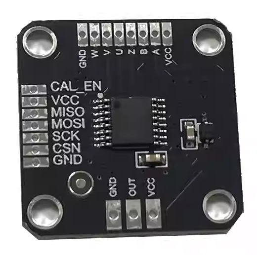
Pin Configuration and Descriptions
The MT6835 is typically available in a compact package with the following pinout:
| Pin | Name | Description |
|---|---|---|
| 1 | VDD | Power supply input (3.3V to 5.5V). |
| 2 | GND | Ground connection. |
| 3 | SCK | SPI clock input (used in SPI communication mode). |
| 4 | MISO | SPI data output (Master In Slave Out). |
| 5 | MOSI | SPI data input (Master Out Slave In). |
| 6 | PWM | Pulse Width Modulation output (used in PWM mode). |
| 7 | A | Quadrature output channel A (used in ABZ mode). |
| 8 | B | Quadrature output channel B (used in ABZ mode). |
| 9 | Z | Index pulse output (used in ABZ mode). |
| 10 | U | UVW output channel U (used in UVW mode). |
| 11 | V | UVW output channel V (used in UVW mode). |
| 12 | W | UVW output channel W (used in UVW mode). |
| 13 | CS | Chip Select (used in SPI communication mode). |
| 14 | NC | No connection (leave unconnected or as specified in the datasheet). |
Usage Instructions
How to Use the MT6835 in a Circuit
- Power Supply: Connect the VDD pin to a regulated 3.3V to 5.5V power source and the GND pin to the ground.
- Magnet Placement: Place a diametrically magnetized magnet on the rotating shaft. Ensure the magnet is aligned with the encoder's sensing surface and within the specified magnetic field strength (30mT to 70mT).
- Output Mode Selection: Choose the desired output mode (SPI, PWM, ABZ, or UVW) based on your application. Connect the corresponding pins to your microcontroller or motor driver.
- SPI Communication: If using SPI mode, connect the SCK, MISO, MOSI, and CS pins to the SPI interface of your microcontroller.
- Quadrature or UVW Outputs: For ABZ or UVW modes, connect the respective output pins (A, B, Z, U, V, W) to your motor controller or feedback system.
Important Considerations and Best Practices
- Magnet Alignment: Ensure the magnet is properly centered and aligned with the encoder to achieve accurate readings.
- Magnetic Field Strength: Use a magnet with the recommended field strength (30mT to 70mT) for optimal performance.
- Decoupling Capacitor: Place a 0.1µF decoupling capacitor close to the VDD and GND pins to reduce noise and improve stability.
- Operating Temperature: Ensure the encoder operates within the specified temperature range (-40°C to +125°C).
- Output Filtering: If using PWM or analog outputs, consider adding a low-pass filter to smooth the signal.
Example: Connecting MT6835 to Arduino UNO (SPI Mode)
Below is an example of how to connect and read data from the MT6835 using an Arduino UNO in SPI mode:
Circuit Connections
| MT6835 Pin | Arduino UNO Pin |
|---|---|
| VDD | 5V |
| GND | GND |
| SCK | D13 (SCK) |
| MISO | D12 (MISO) |
| MOSI | D11 (MOSI) |
| CS | D10 (Chip Select) |
Arduino Code
#include <SPI.h>

// Define MT6835 pins
const int CS_PIN = 10; // Chip Select pin

void setup() {
  Serial.begin(9600); // Initialize serial communication
  SPI.begin();        // Initialize SPI
  pinMode(CS_PIN, OUTPUT);
  digitalWrite(CS_PIN, HIGH); // Set CS pin high
}

void loop() {
  uint16_t position = readMT6835(); // Read position data
  Serial.print("Position: ");
  Serial.println(position); // Print position to serial monitor
  delay(100); // Delay for readability
}

// Function to read position data from MT6835
uint16_t readMT6835() {
  digitalWrite(CS_PIN, LOW); // Select the MT6835
  delayMicroseconds(1);      // Small delay for stability

  // Send command to read position (example: 0xFFFF)
  uint16_t command = 0xFFFF;
  uint16_t response = SPI.transfer16(command);

  digitalWrite(CS_PIN, HIGH); // Deselect the MT6835
  return response;            // Return the position data
}
Troubleshooting and FAQs
Common Issues and Solutions
No Output or Incorrect Readings:
- Ensure the magnet is properly aligned and within the specified magnetic field strength.
- Verify all connections, especially power (VDD and GND) and communication lines (SPI, PWM, etc.).
- Check that the encoder is operating within the specified voltage and temperature ranges.
Noise or Unstable Output:
- Add a decoupling capacitor (0.1µF) near the VDD and GND pins.
- Use shielded cables for long connections to reduce electromagnetic interference.
SPI Communication Fails:
- Verify the SPI clock speed is within the encoder's supported range.
- Ensure the CS pin is toggled correctly during communication.
FAQs
Q: Can the MT6835 be used with a non-diametrically magnetized magnet?
A: No, the MT6835 requires a diametrically magnetized magnet for accurate position sensing.
Q: What is the maximum resolution of the MT6835?
A: The MT6835 supports up to 14-bit resolution, providing 16,384 distinct positions per revolution.
Q: Can the MT6835 measure linear motion?
A: The MT6835 is designed for rotational position sensing. For linear motion, additional mechanical conversion is required.
Q: Is the MT6835 compatible with 3.3V systems?
A: Yes, the MT6835 operates with a supply voltage range of 3.3V to 5.5V, making it compatible with both 3.3V and 5V systems.