Cirkit Designer Logo
Cirkit Designer
Your all-in-one circuit design IDE
Home / 
Component Documentation

How to Use Olimex ESP32-EVB: Examples, Pinouts, and Specs

Image of Olimex ESP32-EVB
Cirkit Designer LogoDesign with Olimex ESP32-EVB in Cirkit Designer

Introduction

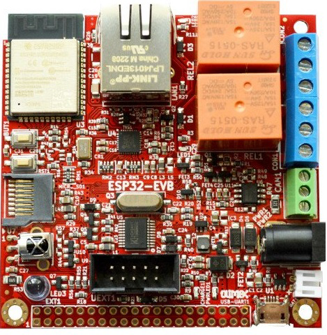
The Olimex ESP32-EVB is a versatile development board that harnesses the power of the ESP32 microcontroller. This board is designed for a wide range of applications, from IoT devices to complex networking projects, thanks to its built-in Wi-Fi and Bluetooth capabilities. It is an excellent choice for both hobbyists and professionals looking to develop prototypes or final products with wireless connectivity and a multitude of GPIO options.

Explore Projects Built with Olimex ESP32-EVB

Use Cirkit Designer to design, explore, and prototype these projects online. Some projects support real-time simulation. Click "Open Project" to start designing instantly!
ESP32-Based Multi-Sensor Health Monitoring System with Bluetooth Connectivity
Image of circuit diagram: A project utilizing Olimex ESP32-EVB in a practical application
This circuit features an ESP32-WROOM-32UE microcontroller as the central processing unit, interfacing with a variety of sensors and modules. It includes a MAX30100 pulse oximeter and heart-rate sensor, an MLX90614 infrared thermometer, an HC-05 Bluetooth module for wireless communication, and a Neo 6M GPS module for location tracking. All components are powered by a common voltage supply and are connected to specific GPIO pins on the ESP32 for data exchange, with the sensors using I2C communication and the modules using UART.
Cirkit Designer LogoOpen Project in Cirkit Designer
ESP32-Based Sensor Monitoring System with OLED Display and E-Stop
Image of MVP_design: A project utilizing Olimex ESP32-EVB in a practical application
This circuit features an ESP32 microcontroller that interfaces with a variety of sensors and output devices. It is powered by a Lipo battery through a buck converter, ensuring a stable voltage supply. The ESP32 collects data from a DHT11 temperature and humidity sensor and a vibration sensor, controls a buzzer, and displays information on an OLED screen. An emergency stop (E Stop) is connected for safety purposes, allowing the system to be quickly deactivated.
Cirkit Designer LogoOpen Project in Cirkit Designer
ESP32-Based Health Monitoring System with Touch Interface
Image of HEALTH  MONITORING  SYSTEM : A project utilizing Olimex ESP32-EVB in a practical application
This circuit features an ESP32 Devkit V1 microcontroller connected to a MAX30100 pulse oximeter sensor, an mlx90614 infrared thermometer, a 128x64 OLED display, and four TTP233 touch sensors. The ESP32 facilitates communication with the I2C devices (MAX30100, mlx90614, OLED display) using its dedicated SDA and SCL pins, and it interfaces with each touch sensor through individual GPIO pins. The circuit is likely designed for a health monitoring system with touch input capability and visual output on the OLED display.
Cirkit Designer LogoOpen Project in Cirkit Designer
ESP32-Based LoRa Communication Device with OLED Display
Image of LoRa_Satellite_GS: A project utilizing Olimex ESP32-EVB in a practical application
This circuit features an ESP32 microcontroller connected to a 0.96" OLED display and a LoRa Ra-02 SX1278 module for wireless communication. The ESP32 facilitates communication with the OLED display via I2C (SDA and SCK lines) and with the LoRa module via SPI (MISO, MOSI, SCK, NSS lines) and GPIO for control signals (DI00, DI01, RST). The circuit is designed for applications requiring wireless data transmission and visual data display.
Cirkit Designer LogoOpen Project in Cirkit Designer

Explore Projects Built with Olimex ESP32-EVB

Use Cirkit Designer to design, explore, and prototype these projects online. Some projects support real-time simulation. Click "Open Project" to start designing instantly!
Image of circuit diagram: A project utilizing Olimex ESP32-EVB in a practical application
ESP32-Based Multi-Sensor Health Monitoring System with Bluetooth Connectivity
This circuit features an ESP32-WROOM-32UE microcontroller as the central processing unit, interfacing with a variety of sensors and modules. It includes a MAX30100 pulse oximeter and heart-rate sensor, an MLX90614 infrared thermometer, an HC-05 Bluetooth module for wireless communication, and a Neo 6M GPS module for location tracking. All components are powered by a common voltage supply and are connected to specific GPIO pins on the ESP32 for data exchange, with the sensors using I2C communication and the modules using UART.
Cirkit Designer LogoOpen Project in Cirkit Designer
Image of MVP_design: A project utilizing Olimex ESP32-EVB in a practical application
ESP32-Based Sensor Monitoring System with OLED Display and E-Stop
This circuit features an ESP32 microcontroller that interfaces with a variety of sensors and output devices. It is powered by a Lipo battery through a buck converter, ensuring a stable voltage supply. The ESP32 collects data from a DHT11 temperature and humidity sensor and a vibration sensor, controls a buzzer, and displays information on an OLED screen. An emergency stop (E Stop) is connected for safety purposes, allowing the system to be quickly deactivated.
Cirkit Designer LogoOpen Project in Cirkit Designer
Image of HEALTH  MONITORING  SYSTEM : A project utilizing Olimex ESP32-EVB in a practical application
ESP32-Based Health Monitoring System with Touch Interface
This circuit features an ESP32 Devkit V1 microcontroller connected to a MAX30100 pulse oximeter sensor, an mlx90614 infrared thermometer, a 128x64 OLED display, and four TTP233 touch sensors. The ESP32 facilitates communication with the I2C devices (MAX30100, mlx90614, OLED display) using its dedicated SDA and SCL pins, and it interfaces with each touch sensor through individual GPIO pins. The circuit is likely designed for a health monitoring system with touch input capability and visual output on the OLED display.
Cirkit Designer LogoOpen Project in Cirkit Designer
Image of LoRa_Satellite_GS: A project utilizing Olimex ESP32-EVB in a practical application
ESP32-Based LoRa Communication Device with OLED Display
This circuit features an ESP32 microcontroller connected to a 0.96" OLED display and a LoRa Ra-02 SX1278 module for wireless communication. The ESP32 facilitates communication with the OLED display via I2C (SDA and SCK lines) and with the LoRa module via SPI (MISO, MOSI, SCK, NSS lines) and GPIO for control signals (DI00, DI01, RST). The circuit is designed for applications requiring wireless data transmission and visual data display.
Cirkit Designer LogoOpen Project in Cirkit Designer

Common Applications and Use Cases

  • Internet of Things (IoT) devices
  • Home automation systems
  • Wireless sensor networks
  • Bluetooth-enabled products
  • Rapid prototyping for embedded systems

Technical Specifications

Key Technical Details

  • Microcontroller: ESP32
  • Operating Voltage: 3.3V
  • Input Voltage: 5V via micro USB or PoE
  • Digital I/O Pins: 40
  • Analog Input Pins: 12 (VP, VN, 32, 33, 34, 35, 36, 39)
  • Analog Output Pins: 2 (DAC1, DAC2)
  • Flash Memory: 4MB
  • SRAM: 520 KB
  • Clock Speed: 240 MHz
  • Wi-Fi: 802.11 b/g/n
  • Bluetooth: v4.2 BR/EDR and BLE
  • Ethernet: 100Mb interface with PoE capability

Pin Configuration and Descriptions

Pin Number Function Description
1-40 GPIO General Purpose Input/Output pins
41-52 Power, Reset Power supply, Ground, and Reset pins
53-60 Communication UART, SPI, I2C, and CAN interface pins
61-64 Analog Inputs Analog-to-Digital Converter (ADC) pins
65-66 Analog Outputs Digital-to-Analog Converter (DAC) pins
67-68 Ethernet Ethernet TX and RX pins
69 Micro SD Card Micro SD card interface
70-73 USB USB interface and programming pins

Usage Instructions

How to Use the Component in a Circuit

  1. Powering the Board:

    • Connect a 5V power supply to the micro USB port or use the PoE feature if available.
  2. Programming the Board:

    • Install the necessary drivers and the Arduino IDE or ESP-IDF.
    • Select the correct board and port in your development environment.
    • Use a micro USB cable to connect the board to your computer for programming.
  3. Interfacing with External Components:

    • Use the GPIO pins to connect sensors, actuators, or other peripherals.
    • Ensure that the voltage levels are compatible with the board's 3.3V logic.
  4. Wireless Connectivity:

    • Utilize the Wi-Fi and Bluetooth functionalities by including the appropriate libraries in your code.

Important Considerations and Best Practices

  • Always ensure that the power supply is within the specified range to prevent damage.
  • When interfacing with 5V components, use level shifters to avoid damaging the 3.3V logic pins.
  • Use decoupling capacitors close to the power pins to minimize noise and voltage spikes.
  • Avoid drawing more than 12 mA from any GPIO pin.
  • For Wi-Fi and Bluetooth applications, ensure that the antenna area is not obstructed to maintain signal integrity.

Troubleshooting and FAQs

Common Issues

  • Board Not Recognized by Computer:

    • Check the USB cable and port.
    • Ensure that the correct drivers are installed.
  • Wi-Fi or Bluetooth Not Working:

    • Verify that the antenna is not obstructed.
    • Check your code for proper initialization of wireless functionalities.
  • GPIO Pin Not Functioning:

    • Ensure that the pin is not being used by another peripheral (e.g., SD card or USB).
    • Check for soldering issues or shorts on the board.

Solutions and Tips for Troubleshooting

  • Always start with a simple blink program to ensure the board is functioning correctly.
  • Use serial output to debug and track down issues in your code.
  • Consult the Olimex ESP32-EVB forums and community for help with specific problems.

FAQs

  • Q: Can I power the board through the GPIO pins?

    • A: It is not recommended to power the board through GPIO pins. Use the designated power input methods.
  • Q: How do I enable PoE on the board?

    • A: To enable PoE, you need a PoE-compliant router or injector and ensure that the board's PoE option is configured correctly.
  • Q: What is the maximum range of the Wi-Fi and Bluetooth signals?

    • A: The range depends on environmental factors, but typically Wi-Fi can reach up to 50 meters indoors, and Bluetooth has a range of about 10 meters.

Example Code for Arduino UNO

// Basic Wi-Fi connection example for the Olimex ESP32-EVB

#include <WiFi.h>

// Replace with your network credentials
const char* ssid = "your_SSID";
const char* password = "your_PASSWORD";

void setup() {
  Serial.begin(115200);
  
  // Connect to Wi-Fi
  WiFi.begin(ssid, password);
  
  while (WiFi.status() != WL_CONNECTED) {
    delay(500);
    Serial.println("Connecting to WiFi...");
  }
  
  Serial.println("Connected to WiFi");
}

void loop() {
  // Put your main code here, to run repeatedly:
}

Remember to replace your_SSID and your_PASSWORD with your actual Wi-Fi network credentials. This code will connect your Olimex ESP32-EVB to your Wi-Fi network and print a confirmation message to the serial monitor.