How to Use RJ45 TO TERMINAL: Examples, Pinouts, and Specs
Introduction
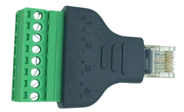
The RJ45 to Terminal adapter is a versatile connector that bridges RJ45 Ethernet cables with terminal blocks. This component is widely used to integrate network devices into wired networks without requiring soldering or specialized tools. It simplifies the process of connecting Ethernet cables to custom circuits, industrial equipment, or other non-standard networking setups.
Explore Projects Built with RJ45 TO TERMINAL

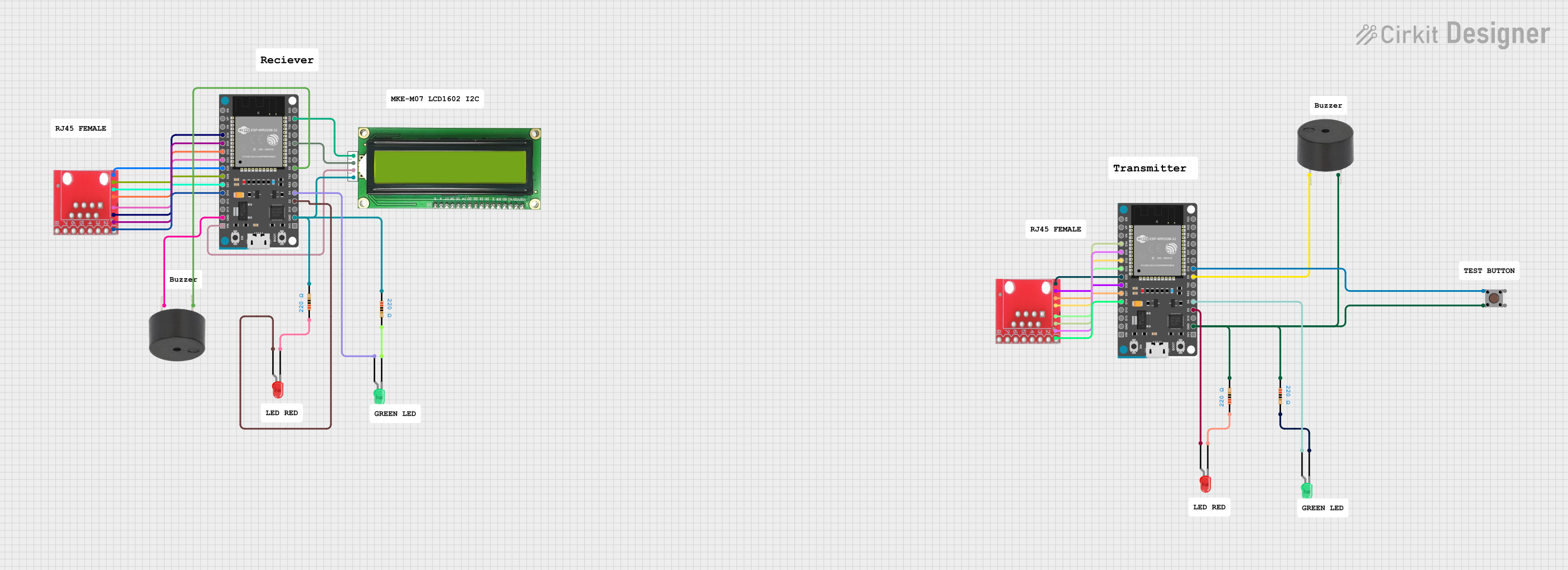


Explore Projects Built with RJ45 TO TERMINAL
Common Applications and Use Cases
- Connecting Ethernet-enabled devices to custom circuits or industrial control systems.
- Prototyping and testing Ethernet-based projects.
- Extending or adapting Ethernet connections in non-standard environments.
- Interfacing Ethernet cables with microcontrollers or other hardware.
Technical Specifications
The RJ45 to Terminal adapter is designed to provide a reliable and straightforward connection between Ethernet cables and terminal blocks. Below are the key technical details:
General Specifications
| Parameter | Value |
|---|---|
| Connector Type | RJ45 (8P8C) to Terminal Block |
| Supported Ethernet Type | Cat5, Cat5e, Cat6 |
| Number of Terminals | 8 (1 for each RJ45 pin) |
| Material | Plastic housing, copper terminals |
| Dimensions | Varies by model (e.g., 50x20x15 mm) |
| Operating Temperature | -20°C to 70°C |
Pin Configuration and Descriptions
The RJ45 to Terminal adapter maps the 8 pins of the RJ45 connector to individual screw terminals. Below is the pinout:
| RJ45 Pin | Terminal Block Pin | Signal Name | Description |
|---|---|---|---|
| 1 | 1 | TX+ | Transmit Data Positive |
| 2 | 2 | TX- | Transmit Data Negative |
| 3 | 3 | RX+ | Receive Data Positive |
| 4 | 4 | Unused (PoE+) | Power over Ethernet Positive (if used) |
| 5 | 5 | Unused (PoE+) | Power over Ethernet Positive (if used) |
| 6 | 6 | RX- | Receive Data Negative |
| 7 | 7 | Unused (PoE-) | Power over Ethernet Negative (if used) |
| 8 | 8 | Unused (PoE-) | Power over Ethernet Negative (if used) |
Usage Instructions
How to Use the RJ45 to Terminal Adapter in a Circuit
- Prepare the Ethernet Cable: Ensure the RJ45 Ethernet cable is properly terminated and tested for continuity.
- Connect the RJ45 Plug: Insert the RJ45 plug into the adapter's RJ45 socket until it clicks securely.
- Wire the Terminal Block:
- Loosen the screws on the terminal block using a small screwdriver.
- Insert the corresponding wires into the terminal block based on the pinout table above.
- Tighten the screws to secure the wires.
- Verify Connections: Double-check the wiring to ensure the correct mapping of signals.
- Integrate into Circuit: Connect the terminal block to your circuit or device as needed.
Important Considerations and Best Practices
- Signal Integrity: Use high-quality Ethernet cables to minimize signal loss or interference.
- PoE Compatibility: If using Power over Ethernet (PoE), ensure the connected device supports the required voltage and current.
- Avoid Over-Tightening: Do not overtighten the terminal screws, as this may damage the wires or the terminal block.
- Label Wires: For complex setups, label the wires to avoid confusion during installation or troubleshooting.
Example: Connecting to an Arduino UNO
The RJ45 to Terminal adapter can be used to interface an Ethernet cable with an Arduino UNO via an Ethernet shield. Below is an example of how to use the adapter in such a setup:
#include <SPI.h>
#include <Ethernet.h>

// MAC address and IP address for the Ethernet shield
byte mac[] = { 0xDE, 0xAD, 0xBE, 0xEF, 0xFE, 0xED };
IPAddress ip(192, 168, 1, 177);

// Initialize the Ethernet server on port 80
EthernetServer server(80);

void setup() {
  // Start the Ethernet connection
  Ethernet.begin(mac, ip);

  // Start the server
  server.begin();

  // Print the IP address to the Serial Monitor
  Serial.begin(9600);
  Serial.print("Server is at ");
  Serial.println(Ethernet.localIP());
}

void loop() {
  // Listen for incoming clients
  EthernetClient client = server.available();
  if (client) {
    // Handle client requests
    Serial.println("New client connected");
    while (client.connected()) {
      if (client.available()) {
        char c = client.read();
        Serial.write(c); // Echo data to Serial Monitor
      }
    }
    client.stop();
    Serial.println("Client disconnected");
  }
}
Troubleshooting and FAQs
Common Issues and Solutions
No Connection or Intermittent Signal
- Cause: Loose or incorrect wiring.
- Solution: Verify the wiring against the pinout table and ensure all screws are tightened securely.
Ethernet Device Not Powering On (PoE Setup)
- Cause: Insufficient power or incorrect PoE wiring.
- Solution: Check the power supply and ensure the PoE pins are correctly wired.
Signal Interference or Data Loss
- Cause: Low-quality cables or long cable runs.
- Solution: Use shielded Ethernet cables and keep cable lengths within recommended limits.
RJ45 Plug Does Not Fit Securely
- Cause: Damaged or incompatible RJ45 plug.
- Solution: Inspect the plug for damage and replace if necessary.
FAQs
Q: Can this adapter be used with Cat7 cables?
A: While the adapter is primarily designed for Cat5, Cat5e, and Cat6 cables, it may work with Cat7 cables if the connectors are compatible.
Q: Is this adapter suitable for outdoor use?
A: The adapter is not weatherproof. For outdoor use, ensure it is housed in a weatherproof enclosure.
Q: Can I use this adapter for non-Ethernet signals?
A: Yes, the adapter can be used for other signals, but ensure the voltage and current ratings are within safe limits.
Q: Does this adapter support Gigabit Ethernet?
A: Yes, it supports Gigabit Ethernet, provided the connected cables and devices are compatible.