How to Use Touch Sensor TP233: Examples, Pinouts, and Specs

Introduction
The TP233 is a capacitive touch sensor designed to detect touch input and convert it into an electrical signal. It is widely used in user interfaces for electronic devices, offering a simple and reliable way to replace traditional mechanical buttons. The TP233 is compact, energy-efficient, and highly sensitive, making it ideal for applications such as touch panels, home automation systems, and wearable devices.
Explore Projects Built with Touch Sensor TP233
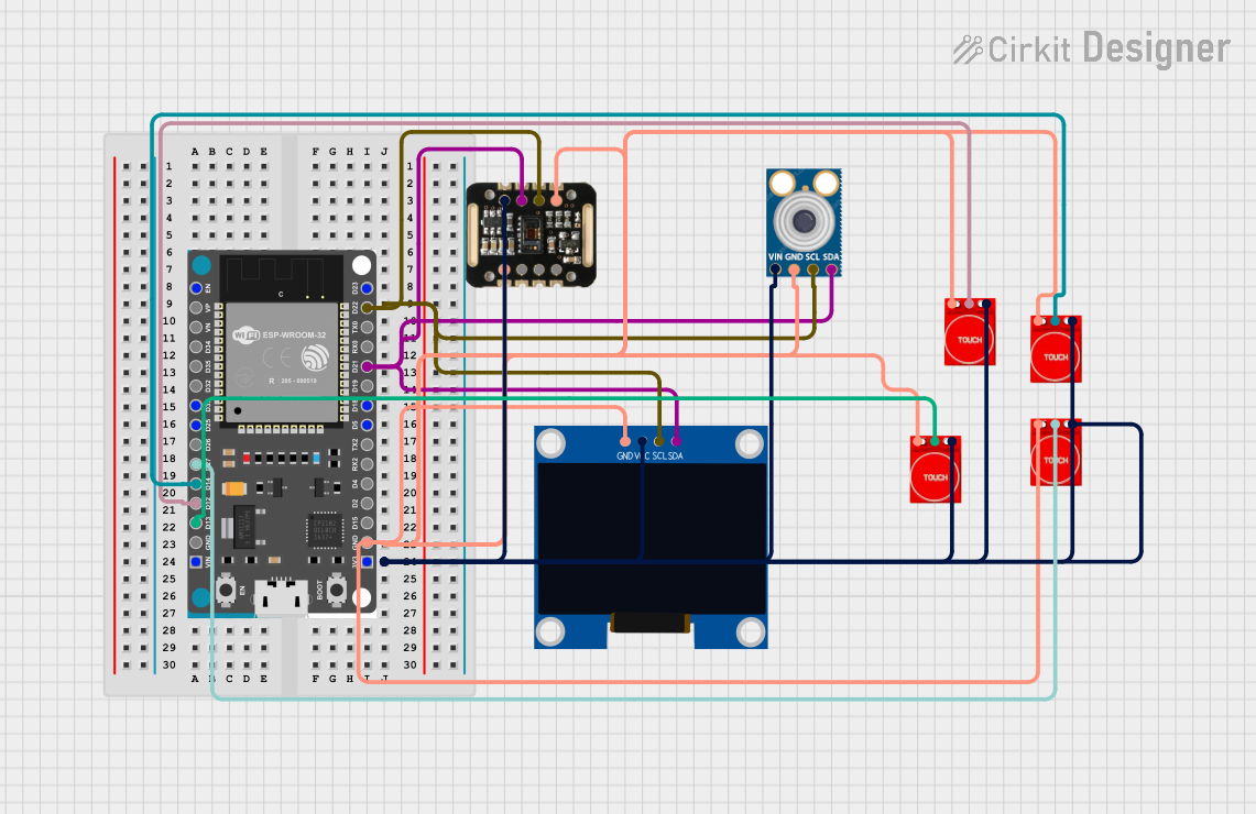

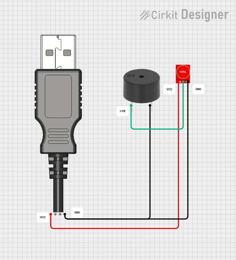
Explore Projects Built with Touch Sensor TP233
Technical Specifications
The TP233 touch sensor is designed for low-power operation and high sensitivity. Below are its key technical details:
General Specifications
| Parameter | Value |
|---|---|
| Operating Voltage | 2.0V to 5.5V |
| Operating Current | < 8 µA (at 3V) |
| Response Time | ~60 ms |
| Output Type | Digital (Active High/Low) |
| Touch Sensitivity | Adjustable via external resistor |
| Operating Temperature | -40°C to +85°C |
Pin Configuration and Descriptions
The TP233 is typically available in an SOT23-6 package. Below is the pinout and description:
| Pin Number | Pin Name | Description |
|---|---|---|
| 1 | VDD | Power supply (2.0V to 5.5V) |
| 2 | OUT | Digital output pin (Active High/Low) |
| 3 | VSS | Ground (0V reference) |
| 4 | TTPAD | Touch input pad (connect to touch electrode) |
| 5 | AHLB | Output mode selection (Active High/Low control) |
| 6 | REXT | External resistor pin for sensitivity adjustment |
Usage Instructions
The TP233 touch sensor is straightforward to use in a circuit. Follow these steps to integrate it into your project:
- Power Supply: Connect the
VDDpin to a 2.0V–5.5V power source and theVSSpin to ground. - Touch Electrode: Attach a conductive material (e.g., copper foil) to the
TTPADpin to act as the touch-sensitive area. - Output Mode: Use the
AHLBpin to configure the output mode:- Connect
AHLBtoVDDfor active-low output. - Connect
AHLBtoVSSfor active-high output.
- Connect
- Sensitivity Adjustment: Connect an external resistor (typically 470 kΩ to 50 MΩ) to the
REXTpin to adjust the touch sensitivity. Lower resistance increases sensitivity. - Output Signal: The
OUTpin provides a digital signal that changes state when a touch is detected.
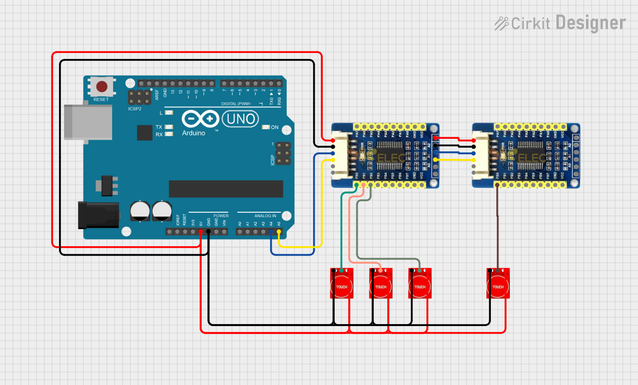
Example Circuit
Below is a basic circuit diagram for using the TP233 with an Arduino UNO:
- Connect
VDDto the Arduino's 5V pin. - Connect
VSSto the Arduino's GND pin. - Connect the
OUTpin to a digital input pin on the Arduino (e.g., D2). - Attach a touch electrode to the
TTPADpin.
Arduino Code Example
The following code demonstrates how to use the TP233 with an Arduino UNO:
// Define the pin connected to the TP233 OUT pin
const int touchPin = 2; // Digital pin 2
const int ledPin = 13;  // Built-in LED pin

void setup() {
  pinMode(touchPin, INPUT); // Set touchPin as input
  pinMode(ledPin, OUTPUT);  // Set ledPin as output
  Serial.begin(9600);       // Initialize serial communication
}

void loop() {
  int touchState = digitalRead(touchPin); // Read the touch sensor state

  if (touchState == HIGH) {
    // If touch is detected, turn on the LED
    digitalWrite(ledPin, HIGH);
    Serial.println("Touch detected!");
  } else {
    // If no touch is detected, turn off the LED
    digitalWrite(ledPin, LOW);
  }

  delay(100); // Small delay to stabilize readings
}
Best Practices
- Use a stable power supply to avoid false triggers.
- Keep the touch electrode away from noise sources (e.g., high-frequency circuits).
- Adjust the sensitivity resistor (
REXT) based on the size and material of the touch electrode.
Troubleshooting and FAQs
Common Issues
False Triggers or No Response
- Cause: Improper sensitivity adjustment.
- Solution: Adjust the
REXTresistor value. Use a lower resistance for higher sensitivity or a higher resistance for lower sensitivity.
Unstable Output
- Cause: Electrical noise or unstable power supply.
- Solution: Add a decoupling capacitor (e.g., 0.1 µF) between
VDDandVSS.
No Output Signal
- Cause: Incorrect wiring or damaged component.
- Solution: Verify all connections and ensure the TP233 is not damaged.
FAQs
Q: Can the TP233 detect multiple touches simultaneously?
A: No, the TP233 is designed to detect a single touch input at a time.
Q: What materials can be used for the touch electrode?
A: Conductive materials such as copper foil, aluminum tape, or conductive ink can be used.
Q: How do I increase the detection range?
A: Increase the size of the touch electrode and adjust the REXT resistor for higher sensitivity.
Q: Can the TP233 work with a 3.3V system?
A: Yes, the TP233 operates within a voltage range of 2.0V to 5.5V, making it compatible with 3.3V systems.
By following this documentation, you can effectively integrate the TP233 touch sensor into your projects and troubleshoot common issues with ease.