
How to Use InvenSense MPU6050: Examples, Pinouts, and Specs
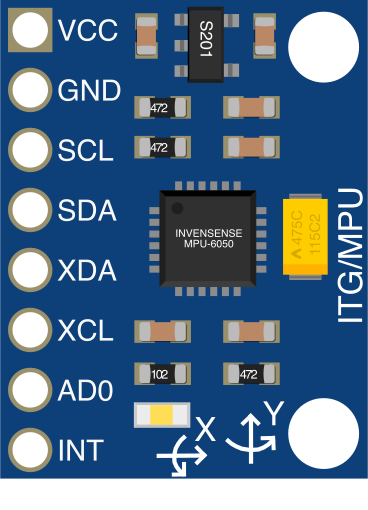
 Design with InvenSense MPU6050 in Cirkit Designer
Introduction
The InvenSense MPU6050 is a 6-axis motion tracking device that integrates a 3-axis gyroscope and a 3-axis accelerometer into a single chip. This compact and versatile sensor is widely used in applications requiring precise motion detection and orientation tracking. Its built-in Digital Motion Processor (DMP) allows for advanced motion processing, reducing the computational load on external microcontrollers.
Explore Projects Built with InvenSense MPU6050
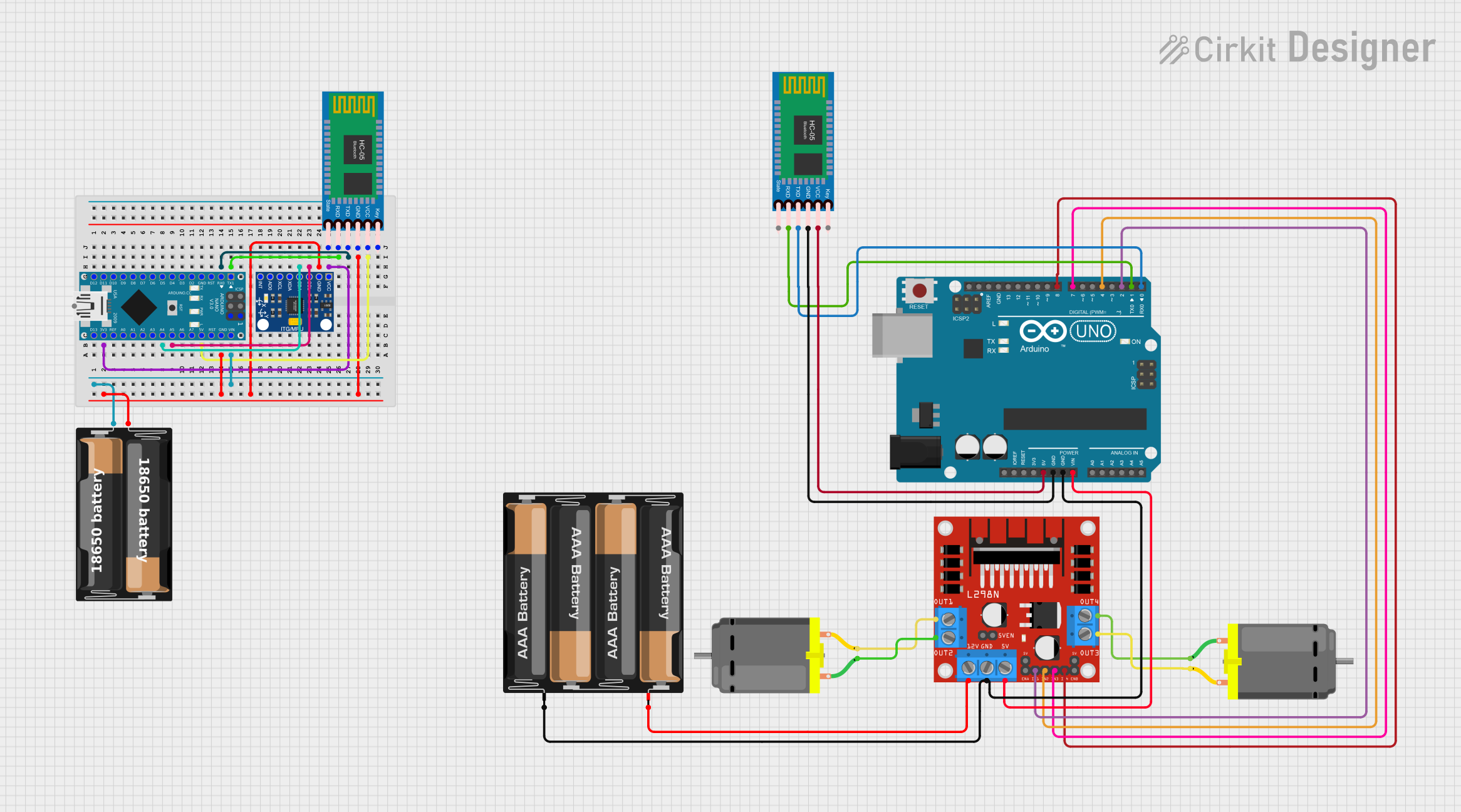 Open Project in Cirkit Designer
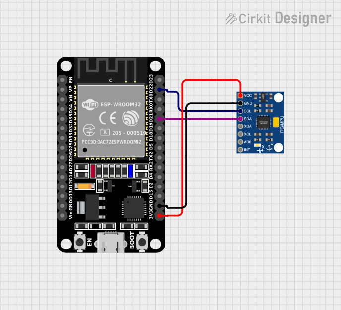 Open Project in Cirkit Designer
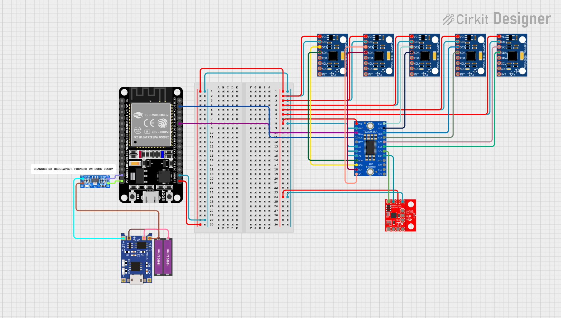 Open Project in Cirkit Designer
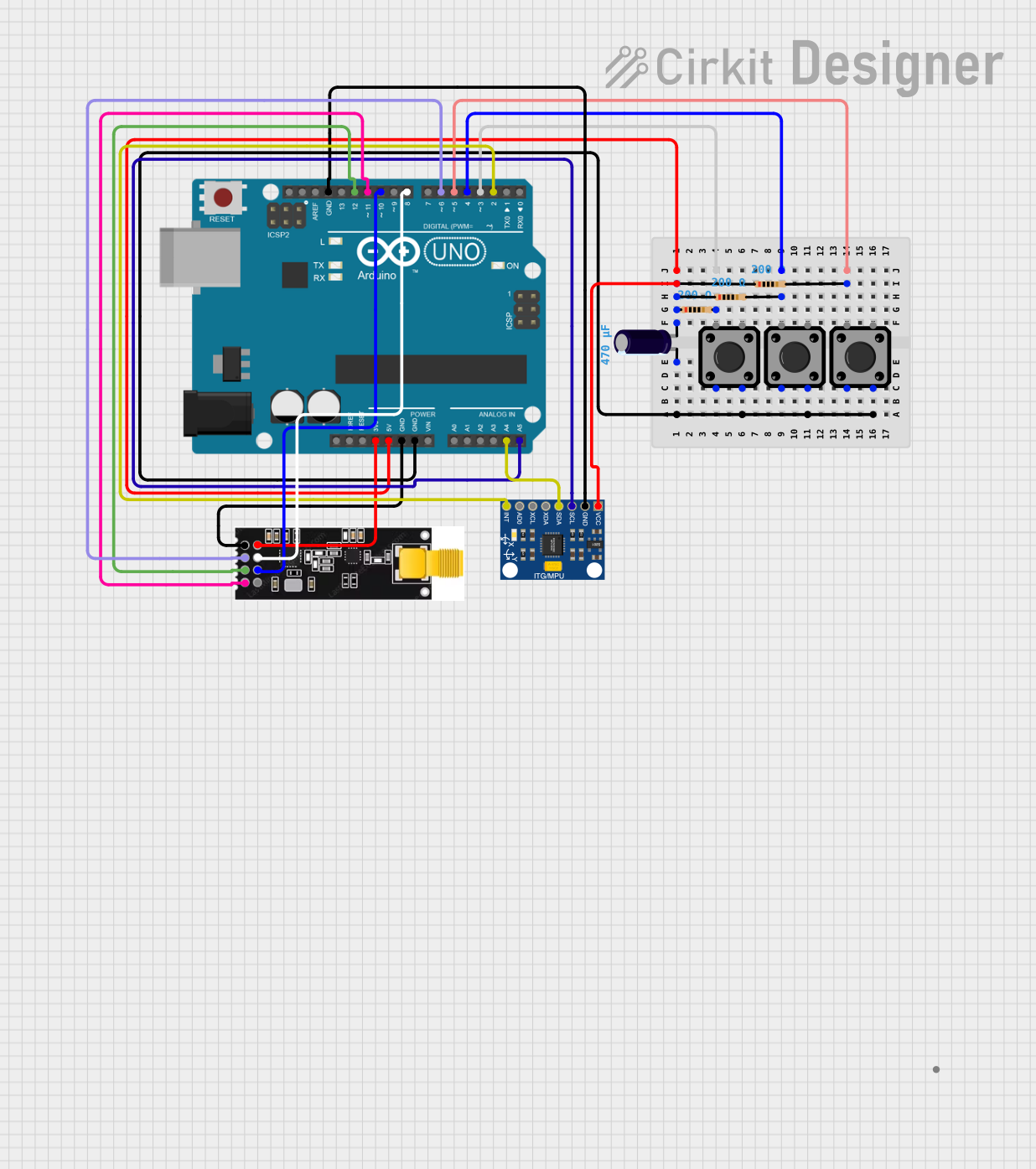 Open Project in Cirkit Designer
Explore Projects Built with InvenSense MPU6050
Open Project in Cirkit DesignerOpen Project in Cirkit DesignerOpen Project in Cirkit DesignerOpen Project in Cirkit DesignerCommon Applications
- Smartphones and tablets for screen orientation and motion-based controls
- Drones for stabilization and navigation
- Gaming controllers for motion-based input
- Robotics for balance and movement tracking
- Wearable devices for fitness and activity monitoring
Technical Specifications
The following table outlines the key technical details of the MPU6050:
| Parameter | Value |
|---|---|
| Manufacturer | InvenSense |
| Part ID | MPU-6050 |
| Supply Voltage (VDD) | 2.375V to 3.46V |
| I/O Voltage (VLOGIC) | 1.8V to VDD |
| Gyroscope Range | ±250, ±500, ±1000, ±2000 °/s |
| Accelerometer Range | ±2g, ±4g, ±8g, ±16g |
| Communication Interface | I2C (up to 400kHz) or SPI |
| Operating Temperature | -40°C to +85°C |
| Package | 4x4x0.9 mm QFN |
Pin Configuration and Descriptions
The MPU6050 has 24 pins, but the most commonly used pins for basic operation are listed below:
| Pin Name | Pin Number | Description |
|---|---|---|
| VDD | 8 | Power supply (2.375V to 3.46V) |
| VLOGIC | 9 | Logic voltage supply (1.8V to VDD) |
| GND | 12 | Ground |
| SCL | 6 | I2C clock line |
| SDA | 7 | I2C data line |
| AD0 | 8 | I2C address select (0: 0x68, 1: 0x69) |
| INT | 22 | Interrupt output |
| FSYNC | 23 | Frame synchronization input |
| CLKIN | 24 | Optional external clock input |
For a complete pinout, refer to the official datasheet.
Usage Instructions
Connecting the MPU6050 to an Arduino UNO
To use the MPU6050 with an Arduino UNO, follow these steps:
- Connect the VDD pin to the Arduino's 3.3V pin.
- Connect the GND pin to the Arduino's GND pin.
- Connect the SCL pin to the Arduino's A5 pin (I2C clock line).
- Connect the SDA pin to the Arduino's A4 pin (I2C data line).
- Optionally, connect the INT pin to a digital pin on the Arduino for interrupt-based operation.
Sample Arduino Code
Below is an example of how to read accelerometer and gyroscope data from the MPU6050 using the Arduino IDE. This code uses the popular Wire library for I2C communication.
#include <Wire.h>

// MPU6050 I2C address (default is 0x68 when AD0 is LOW)
const int MPU6050_ADDR = 0x68;

// MPU6050 register addresses
const int ACCEL_XOUT_H = 0x3B; // Accelerometer X-axis high byte
const int GYRO_XOUT_H = 0x43;  // Gyroscope X-axis high byte

void setup() {
  Wire.begin(); // Initialize I2C communication
  Serial.begin(9600); // Initialize serial communication for debugging

  // Wake up the MPU6050 (set power management register to 0)
  Wire.beginTransmission(MPU6050_ADDR);
  Wire.write(0x6B); // Power management register
  Wire.write(0);    // Set to 0 to wake up the sensor
  Wire.endTransmission();
}

void loop() {
  // Read accelerometer data
  int16_t accelX = readMPU6050(ACCEL_XOUT_H);
  int16_t accelY = readMPU6050(ACCEL_XOUT_H + 2);
  int16_t accelZ = readMPU6050(ACCEL_XOUT_H + 4);

  // Read gyroscope data
  int16_t gyroX = readMPU6050(GYRO_XOUT_H);
  int16_t gyroY = readMPU6050(GYRO_XOUT_H + 2);
  int16_t gyroZ = readMPU6050(GYRO_XOUT_H + 4);

  // Print the data to the Serial Monitor
  Serial.print("Accel: X=");
  Serial.print(accelX);
  Serial.print(" Y=");
  Serial.print(accelY);
  Serial.print(" Z=");
  Serial.println(accelZ);

  Serial.print("Gyro: X=");
  Serial.print(gyroX);
  Serial.print(" Y=");
  Serial.print(gyroY);
  Serial.print(" Z=");
  Serial.println(gyroZ);

  delay(500); // Wait for 500ms before the next reading
}

// Function to read 16-bit data from the MPU6050
int16_t readMPU6050(int reg) {
  Wire.beginTransmission(MPU6050_ADDR);
  Wire.write(reg); // Specify the register to read from
  Wire.endTransmission(false); // Restart I2C communication
  Wire.requestFrom(MPU6050_ADDR, 2); // Request 2 bytes of data

  // Combine the high and low bytes
  int16_t value = (Wire.read() << 8) | Wire.read();
  return value;
}
Important Considerations
- Power Supply: Ensure the MPU6050 is powered within its specified voltage range. Exceeding the limits may damage the device.
- I2C Pull-Up Resistors: Use external pull-up resistors (typically 4.7kΩ) on the SCL and SDA lines if they are not already present on your board.
- Address Selection: The I2C address can be set to 0x68 (default) or 0x69 by connecting the AD0 pin to GND or VDD, respectively.
- Mounting Orientation: Properly align the sensor on your PCB to ensure accurate motion readings.
Troubleshooting and FAQs
Common Issues
No Data from the Sensor
- Ensure the MPU6050 is properly powered and connected to the microcontroller.
- Verify the I2C address matches the configuration in your code.
- Check for loose or incorrect wiring.
Inaccurate Readings
- Calibrate the sensor to account for offsets and biases.
- Minimize vibrations and external noise during operation.
I2C Communication Errors
- Ensure pull-up resistors are present on the SCL and SDA lines.
- Check for conflicting devices on the I2C bus.
FAQs
Q: How do I calibrate the MPU6050?
A: Calibration involves determining and compensating for sensor offsets. Libraries like MPU6050 or MPU6050_DMP6 for Arduino often include calibration functions.
Q: Can I use the MPU6050 with a 5V microcontroller?
A: Yes, but you must use a logic level shifter for the I2C lines to avoid damaging the MPU6050, as it operates at 3.3V logic.
Q: What is the maximum sampling rate of the MPU6050?
A: The MPU6050 supports a maximum sampling rate of 1kHz for both the accelerometer and gyroscope.
By following this documentation, you can effectively integrate the MPU6050 into your projects and troubleshoot common issues. For more advanced features, refer to the official datasheet and application notes.