How to Use Adafruit 1.8" TFT Display Breakout and Shield: Examples, Pinouts, and Specs
Introduction
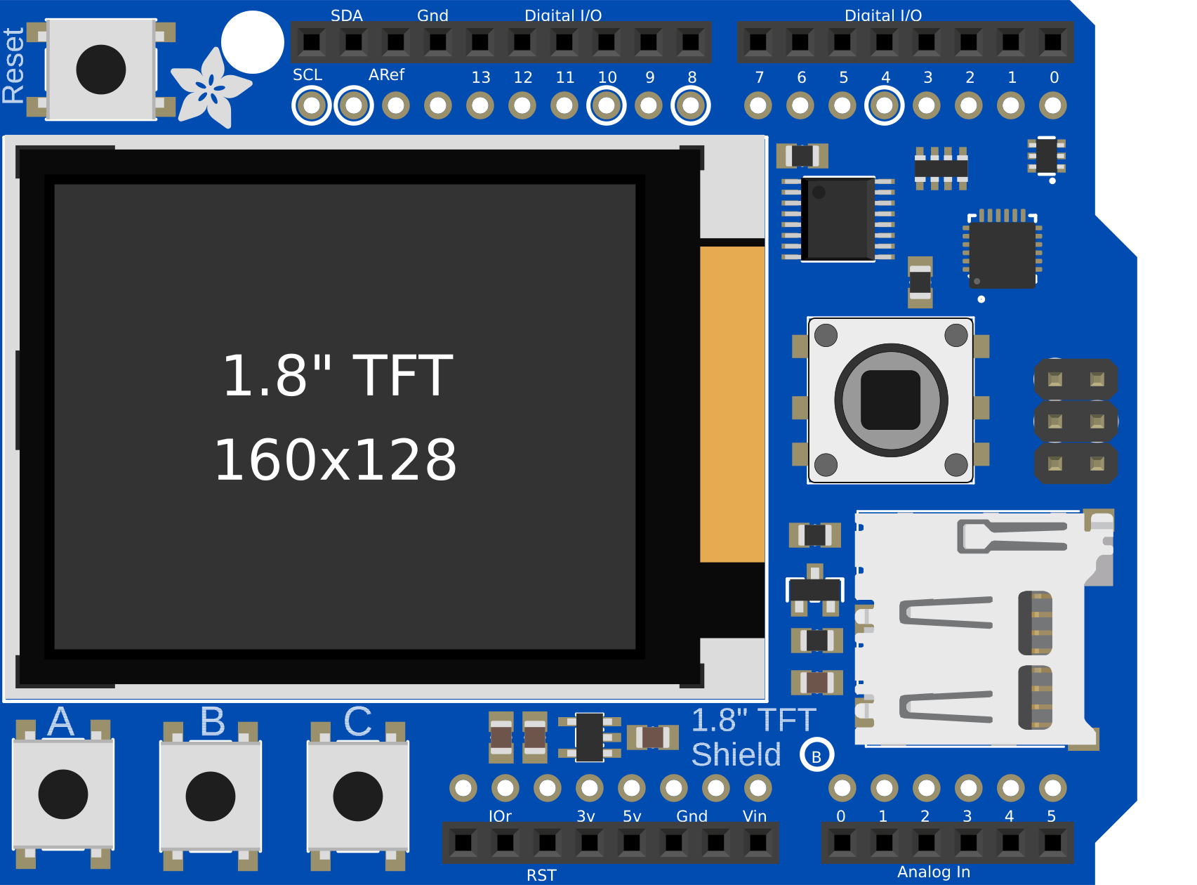
The Adafruit 1.8" TFT Display Breakout and Shield is a compact display module featuring a 1.8-inch TFT screen with a resolution of 128x160 pixels. It is ideal for projects requiring visual output, such as displaying text, images, or simple graphics. This module includes a breakout board for easy connections and is compatible with a wide range of microcontrollers, including Arduino, Raspberry Pi, and others. Its small size and versatility make it an excellent choice for DIY electronics, prototyping, and embedded systems.
Explore Projects Built with Adafruit 1.8" TFT Display Breakout and Shield

Explore Projects Built with Adafruit 1.8" TFT Display Breakout and Shield
Common Applications and Use Cases
- Displaying sensor data in real-time
- Creating graphical user interfaces (GUIs) for embedded systems
- Visual feedback for robotics and automation projects
- Portable gaming devices
- Educational and hobbyist projects
Technical Specifications
Below are the key technical details of the Adafruit 1.8" TFT Display Breakout and Shield:
| Specification | Details |
|---|---|
| Display Type | TFT (Thin-Film Transistor) |
| Screen Size | 1.8 inches |
| Resolution | 128x160 pixels |
| Color Depth | 18-bit (262,144 colors) |
| Interface | SPI (Serial Peripheral Interface) |
| Operating Voltage | 3.3V or 5V (logic level compatible) |
| Backlight | LED, adjustable brightness |
| Dimensions | 50mm x 35mm x 6mm |
| Weight | 10g |
Pin Configuration and Descriptions
The Adafruit 1.8" TFT Display Breakout and Shield has the following pin configuration:
| Pin Name | Description |
|---|---|
| GND | Ground connection |
| VCC | Power supply (3.3V or 5V) |
| SCK | SPI clock signal |
| MOSI | SPI data input (Master Out Slave In) |
| CS | Chip select (active low) |
| DC | Data/Command control pin |
| RST | Reset pin (active low) |
| LED | Backlight control (connect to VCC for full brightness or use PWM for dimming) |
Usage Instructions
How to Use the Component in a Circuit
- Power Supply: Connect the
VCCpin to a 3.3V or 5V power source and theGNDpin to ground. - SPI Communication: Connect the
SCK,MOSI, andCSpins to the corresponding SPI pins on your microcontroller. - Control Pins: Connect the
DCandRSTpins to GPIO pins on your microcontroller. These pins are used to control the display's operation. - Backlight: Connect the
LEDpin to VCC for full brightness or to a PWM-capable pin for adjustable brightness. - Install Libraries: If using an Arduino, install the Adafruit GFX and Adafruit ST7735 libraries from the Arduino Library Manager.
- Upload Code: Use the example code provided below to test the display.
Important Considerations and Best Practices
- Ensure that the logic level of your microcontroller matches the display's input voltage (3.3V or 5V).
- Use short, high-quality wires for SPI connections to minimize noise and ensure reliable communication.
- Avoid exposing the display to excessive heat or moisture.
- Handle the display carefully to prevent damage to the screen or PCB.
Example Code for Arduino UNO
Below is an example code snippet to initialize the display and draw a simple shape:
#include <Adafruit_GFX.h>    // Core graphics library
#include <Adafruit_ST7735.h> // Hardware-specific library for ST7735

// Define pins for the display
#define TFT_CS     10  // Chip select pin
#define TFT_RST    9   // Reset pin
#define TFT_DC     8   // Data/Command pin

// Create an instance of the display
Adafruit_ST7735 tft = Adafruit_ST7735(TFT_CS, TFT_DC, TFT_RST);

void setup() {
  // Initialize the display
  tft.initR(INITR_BLACKTAB); // Initialize with black tab configuration
  tft.fillScreen(ST77XX_BLACK); // Clear the screen with black color

  // Draw a red rectangle
  tft.fillRect(10, 10, 50, 30, ST77XX_RED); // x, y, width, height, color
}

void loop() {
  // Nothing to do here
}
Troubleshooting and FAQs
Common Issues and Solutions
Display Not Turning On:
- Ensure the
VCCandGNDpins are connected properly. - Verify that the power supply provides the correct voltage (3.3V or 5V).
- Ensure the
No Output on the Screen:
- Check the SPI connections (
SCK,MOSI,CS) for loose or incorrect wiring. - Ensure the
DCandRSTpins are connected to the correct GPIO pins. - Confirm that the Adafruit GFX and ST7735 libraries are installed and up to date.
- Check the SPI connections (
Flickering or Unstable Display:
- Use shorter wires for SPI connections to reduce noise.
- Add decoupling capacitors near the power pins if necessary.
Backlight Not Working:
- Verify the connection to the
LEDpin. - If using PWM for dimming, ensure the PWM signal is configured correctly.
- Verify the connection to the
FAQs
Q: Can this display work with 5V logic microcontrollers like Arduino UNO?
A: Yes, the display is compatible with both 3.3V and 5V logic levels.
Q: What is the maximum frame rate supported by the display?
A: The frame rate depends on the SPI clock speed and the complexity of the graphics being rendered. Typically, it can handle up to 30 FPS for simple graphics.
Q: Can I use this display with a Raspberry Pi?
A: Yes, the display is compatible with Raspberry Pi. You can use libraries like Pillow and ST7735 in Python to control it.
Q: How do I adjust the brightness of the backlight?
A: Connect the LED pin to a PWM-capable pin on your microcontroller and adjust the duty cycle of the PWM signal to control brightness.
This concludes the documentation for the Adafruit 1.8" TFT Display Breakout and Shield.