How to Use Buzzer: Examples, Pinouts, and Specs

Introduction
A buzzer is an audio signaling device that produces sound when an electric current passes through it. It is widely used in various applications such as alarms, timers, and notifications. Buzzers are available in two main types: active and passive. Active buzzers generate sound when powered, while passive buzzers require an external signal to produce sound. Their compact size, low power consumption, and ease of use make them a popular choice in electronic projects.
Explore Projects Built with Buzzer

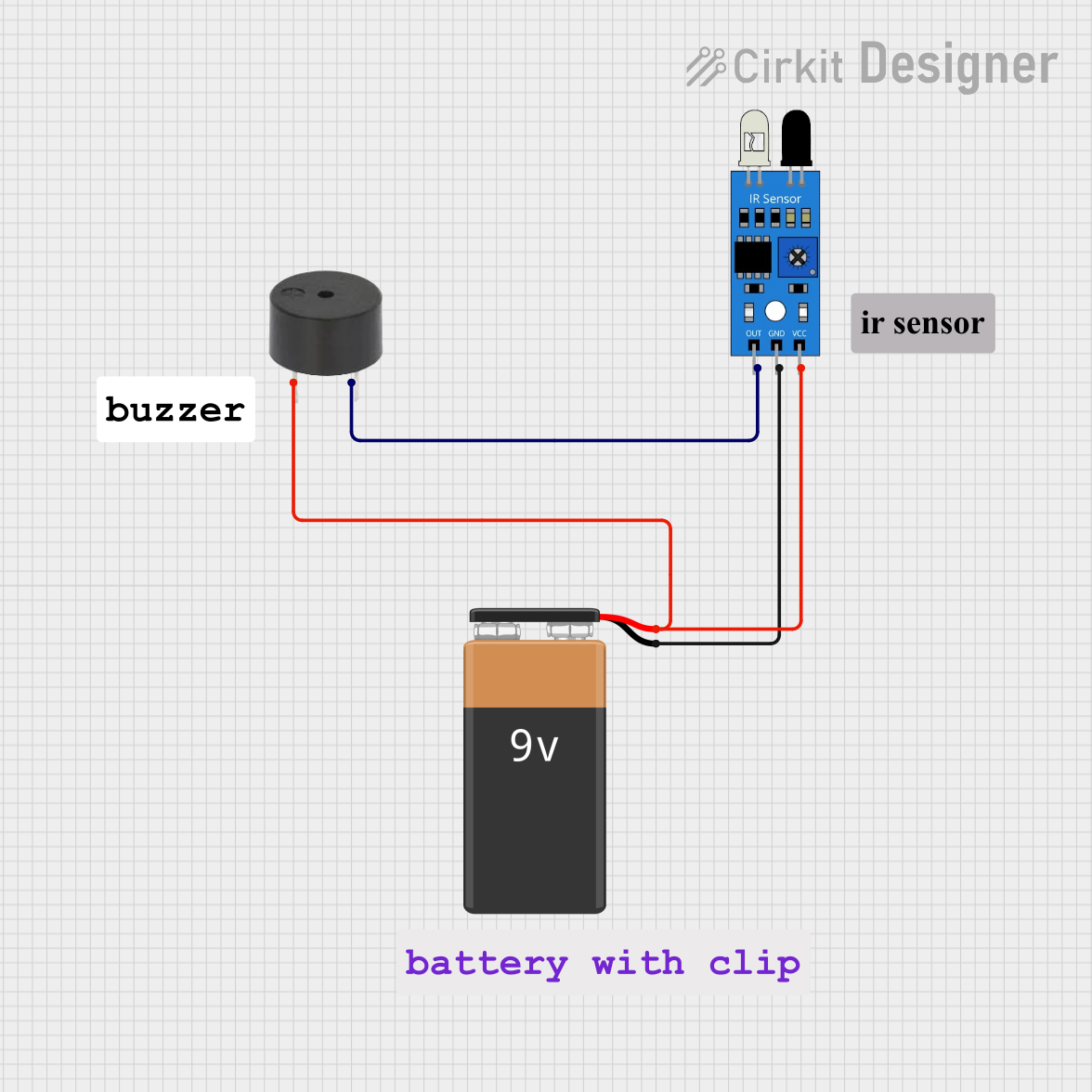
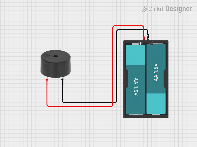

Explore Projects Built with Buzzer
Common Applications
- Alarm systems (e.g., fire alarms, security alarms)
- Timers and reminders
- Notification systems in appliances
- Feedback indicators in electronic devices
- Educational and DIY electronics projects
Technical Specifications
Below are the general technical specifications for a typical buzzer. Note that specific values may vary depending on the model and manufacturer.
| Parameter | Specification |
|---|---|
| Operating Voltage | 3V to 12V (commonly 5V) |
| Current Consumption | 10mA to 50mA |
| Sound Output Level | 85dB to 100dB (at 10cm distance) |
| Frequency Range | 2kHz to 4kHz |
| Operating Temperature | -20°C to +60°C |
| Dimensions | Varies (e.g., 12mm diameter) |
Pin Configuration
Buzzers typically have two pins: a positive (+) and a negative (-) terminal. Below is a table describing the pin configuration:
| Pin | Description |
|---|---|
| Positive (+) | Connect to the positive terminal of the power supply or signal source. |
| Negative (-) | Connect to the ground (GND) of the circuit. |
Usage Instructions
How to Use a Buzzer in a Circuit
- Identify the Type of Buzzer: Determine whether the buzzer is active or passive. Active buzzers only require a DC voltage to operate, while passive buzzers need a PWM (Pulse Width Modulation) signal.
- Connect the Pins:
- Connect the positive (+) pin of the buzzer to the power supply or signal source.
- Connect the negative (-) pin to the ground (GND) of the circuit.
- Power the Circuit: Apply the appropriate voltage to the buzzer. For active buzzers, this will produce a continuous sound. For passive buzzers, use a microcontroller or signal generator to provide a PWM signal.
Important Considerations
- Voltage Compatibility: Ensure the operating voltage of the buzzer matches the power supply to avoid damage.
- Current Limiting: Use a current-limiting resistor if necessary to prevent excessive current draw.
- Mounting: Secure the buzzer in place to avoid vibrations affecting its performance.
- Polarity: Always connect the positive and negative pins correctly to prevent malfunction.
Example: Using a Buzzer with Arduino UNO
Below is an example of how to connect and control a passive buzzer with an Arduino UNO:
Circuit Diagram
- Connect the positive (+) pin of the buzzer to Arduino pin 9.
- Connect the negative (-) pin of the buzzer to GND.
Code Example
// Example code to control a passive buzzer with Arduino UNO
// The buzzer will produce a tone for 1 second, then stop for 1 second.

int buzzerPin = 9; // Pin connected to the buzzer

void setup() {
  pinMode(buzzerPin, OUTPUT); // Set the buzzer pin as an output
}

void loop() {
  tone(buzzerPin, 1000); // Generate a 1kHz tone on the buzzer
  delay(1000);           // Wait for 1 second
  noTone(buzzerPin);     // Stop the tone
  delay(1000);           // Wait for 1 second
}
Notes for Passive Buzzers
- Use the
tone()function to generate sound at a specific frequency. - Use the
noTone()function to stop the sound.
Troubleshooting and FAQs
Common Issues
No Sound from the Buzzer:
- Cause: Incorrect wiring or insufficient voltage.
- Solution: Verify the connections and ensure the power supply matches the buzzer's operating voltage.
Distorted or Weak Sound:
- Cause: Insufficient current or incorrect frequency (for passive buzzers).
- Solution: Check the power supply and ensure the correct frequency is being applied.
Buzzer Overheats:
- Cause: Excessive voltage or current.
- Solution: Use a current-limiting resistor and ensure the voltage is within the specified range.
Buzzer Produces Continuous Sound (Passive Buzzer):
- Cause: A constant DC voltage is applied instead of a PWM signal.
- Solution: Use a microcontroller or signal generator to provide a PWM signal.
FAQs
Q: Can I use a passive buzzer without a microcontroller?
A: Yes, but you will need a signal generator to provide the required frequency. Passive buzzers do not produce sound with a constant DC voltage.
Q: How do I differentiate between an active and a passive buzzer?
A: Active buzzers typically have a built-in oscillator and produce sound when powered with DC voltage. Passive buzzers require an external signal and are usually smaller in size.
Q: Can I use a buzzer with a 3.3V microcontroller?
A: Yes, as long as the buzzer's operating voltage range includes 3.3V. Otherwise, use a transistor or MOSFET to drive the buzzer with a higher voltage.
Q: What is the typical lifespan of a buzzer?
A: Buzzers are highly durable and can last for thousands of hours under normal operating conditions.