How to Use 5V SPDT Relay: Examples, Pinouts, and Specs
5V SPDT Relay Documentation
1. Introduction
The 5V Single Pole Double Throw (SPDT) Relay is an electromechanical switch designed to control high-power circuits using a low-power signal. It is widely used in applications where electrical isolation is required between the control circuit and the load circuit. The relay consists of a coil, a common terminal (COM), a normally closed terminal (NC), and a normally open terminal (NO). When the relay is activated, the internal switch toggles between the NC and NO terminals.
Common Applications:
- Home automation (e.g., controlling lights, fans, or appliances)
- Industrial control systems
- Motor control
- Security systems
- Automotive electronics
- IoT projects with microcontrollers (e.g., Arduino, Raspberry Pi)
2. Technical Specifications
The following table outlines the key technical details of the 5V SPDT relay:
| Parameter | Value |
|---|---|
| Operating Voltage | 5V DC |
| Trigger Voltage | 3.3V to 5V DC |
| Coil Resistance | ~70Ω |
| Switching Voltage (Max) | 250V AC / 30V DC |
| Switching Current (Max) | 10A |
| Contact Type | SPDT (Single Pole Double Throw) |
| Isolation | Electrical isolation between coil and contacts |
| Dimensions | ~19mm x 15mm x 15mm |
| Weight | ~10g |
Pin Configuration and Descriptions
| Pin Name | Description |
|---|---|
| VCC | Connects to the 5V power supply to energize the relay coil. |
| GND | Ground connection for the relay. |
| IN | Control signal input. A HIGH signal activates the relay, switching the contacts. |
| COM | Common terminal. Connect this to the load or power source. |
| NC | Normally Closed terminal. Connected to COM when the relay is inactive. |
| NO | Normally Open terminal. Connected to COM when the relay is active. |
3. Usage Instructions
How to Use the 5V SPDT Relay in a Circuit
Power the Relay:
- Connect the relay's
VCCpin to a 5V DC power supply. - Connect the
GNDpin to the ground of the power supply.
- Connect the relay's
Control Signal:
- Connect the
INpin to a microcontroller's GPIO pin (e.g., Arduino) or any control circuit. - When the control signal is HIGH (5V), the relay activates, switching the internal contacts.
- Connect the
Load Connection:
- Connect the load to the
COMterminal. - Use the
NCterminal if the load should be ON when the relay is inactive. - Use the
NOterminal if the load should be ON when the relay is active.
- Connect the load to the
Isolation:
- Ensure electrical isolation between the control circuit and the load circuit to prevent damage.
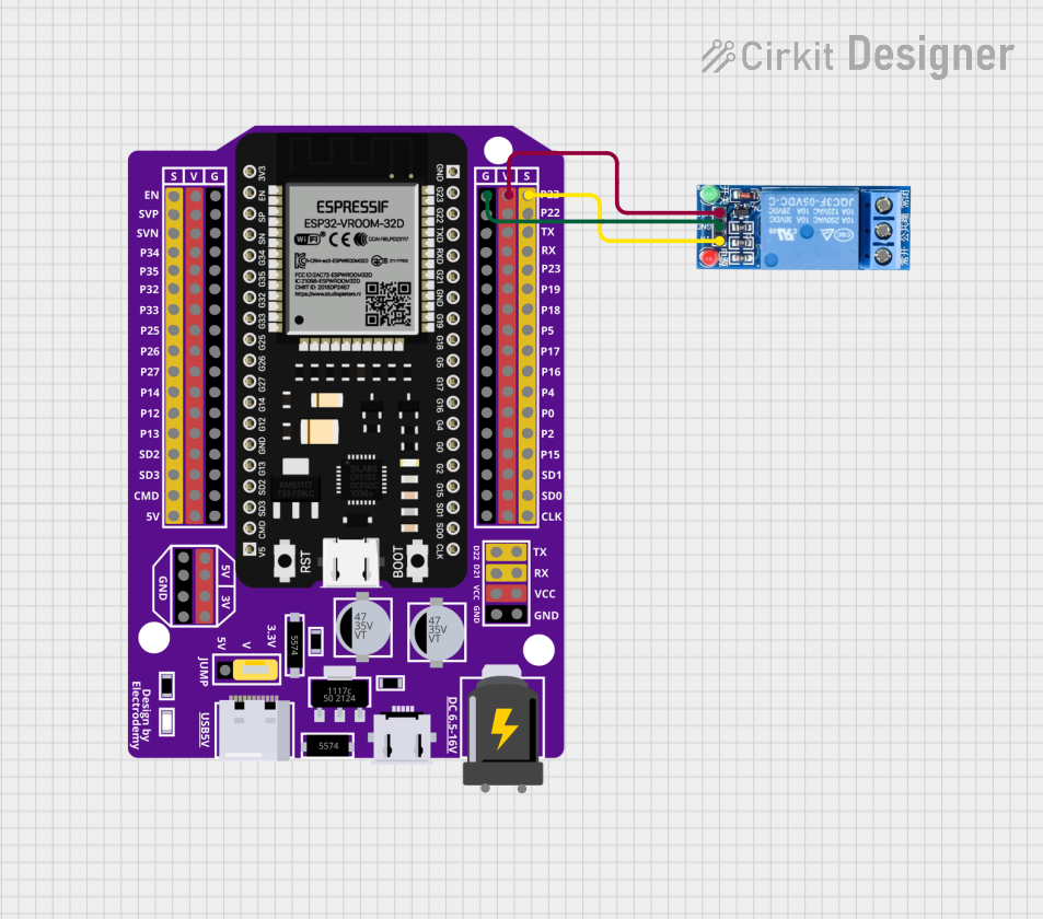
Circuit Diagram Example
Below is a simple circuit diagram for controlling a 230V AC light bulb using an Arduino and a 5V SPDT relay:
Arduino Pin D7 -----> IN (Relay)
5V (Arduino) -------> VCC (Relay)
GND (Arduino) ------> GND (Relay)

COM (Relay) --------> Live wire of the AC load
NO (Relay) ---------> Live wire of the light bulb
Neutral (AC) -------> Neutral wire of the light bulb
Best Practices:
- Use a flyback diode across the relay coil to protect the control circuit from voltage spikes.
- Avoid exceeding the relay's maximum voltage and current ratings.
- Use proper insulation and safety precautions when working with high-voltage loads.
- Use an external transistor or relay driver circuit if the control signal cannot provide sufficient current.
4. Arduino Example Code
The following example demonstrates how to control a 5V SPDT relay using an Arduino UNO:
// Define the relay control pin
const int relayPin = 7; // Connect the relay's IN pin to Arduino pin 7

void setup() {
  pinMode(relayPin, OUTPUT); // Set the relay pin as an output
  digitalWrite(relayPin, LOW); // Ensure the relay is off initially
}

void loop() {
  // Turn the relay ON
  digitalWrite(relayPin, HIGH); // Activates the relay
  delay(5000); // Keep the relay ON for 5 seconds

  // Turn the relay OFF
  digitalWrite(relayPin, LOW); // Deactivates the relay
  delay(5000); // Keep the relay OFF for 5 seconds
}
Code Explanation:
- The relay is connected to pin 7 of the Arduino.
- The
setup()function initializes the relay pin as an output and ensures the relay is OFF initially. - The
loop()function alternates between turning the relay ON and OFF every 5 seconds.
5. Troubleshooting and FAQs
Common Issues and Solutions
| Issue | Possible Cause | Solution |
|---|---|---|
| Relay does not activate | Insufficient control signal voltage or current | Ensure the control signal is 5V and can supply enough current (~15-20mA). |
| Relay clicks but load does not switch | Incorrect wiring of load to COM, NC, or NO terminals | Double-check the wiring of the load to the relay terminals. |
| Arduino resets when relay activates | Voltage spike from the relay coil | Add a flyback diode (e.g., 1N4007) across the relay coil terminals. |
| Relay remains ON or OFF permanently | Damaged relay or incorrect control signal | Replace the relay or verify the control signal logic. |
Frequently Asked Questions
Can I use the 5V SPDT relay with a 3.3V microcontroller?
- Yes, but you may need a transistor or relay driver circuit to boost the control signal to 5V.
What is the purpose of the flyback diode?
- The flyback diode protects the control circuit from voltage spikes generated when the relay coil is de-energized.
Can I control multiple relays with one Arduino?
- Yes, as long as each relay is connected to a separate GPIO pin and the total current draw does not exceed the Arduino's limits.
Is the relay safe for high-voltage applications?
- Yes, but ensure proper insulation and safety precautions when working with high-voltage loads.
6. Conclusion
The 5V SPDT Relay is a versatile and essential component for controlling high-power circuits with low-power signals. Its ability to provide electrical isolation and handle high voltages and currents makes it ideal for a wide range of applications. By following the usage instructions and best practices outlined in this documentation, you can safely and effectively integrate the relay into your projects.
Explore Projects Built with 5V SPDT Relay


Explore Projects Built with 5V SPDT Relay